Cirkit Designer
Your all-in-one circuit design IDE
Home /
Project Documentation
Arduino-Controlled Dual DC Motor Robot with IR and Ultrasonic Sensors
Circuit Documentation
Summary
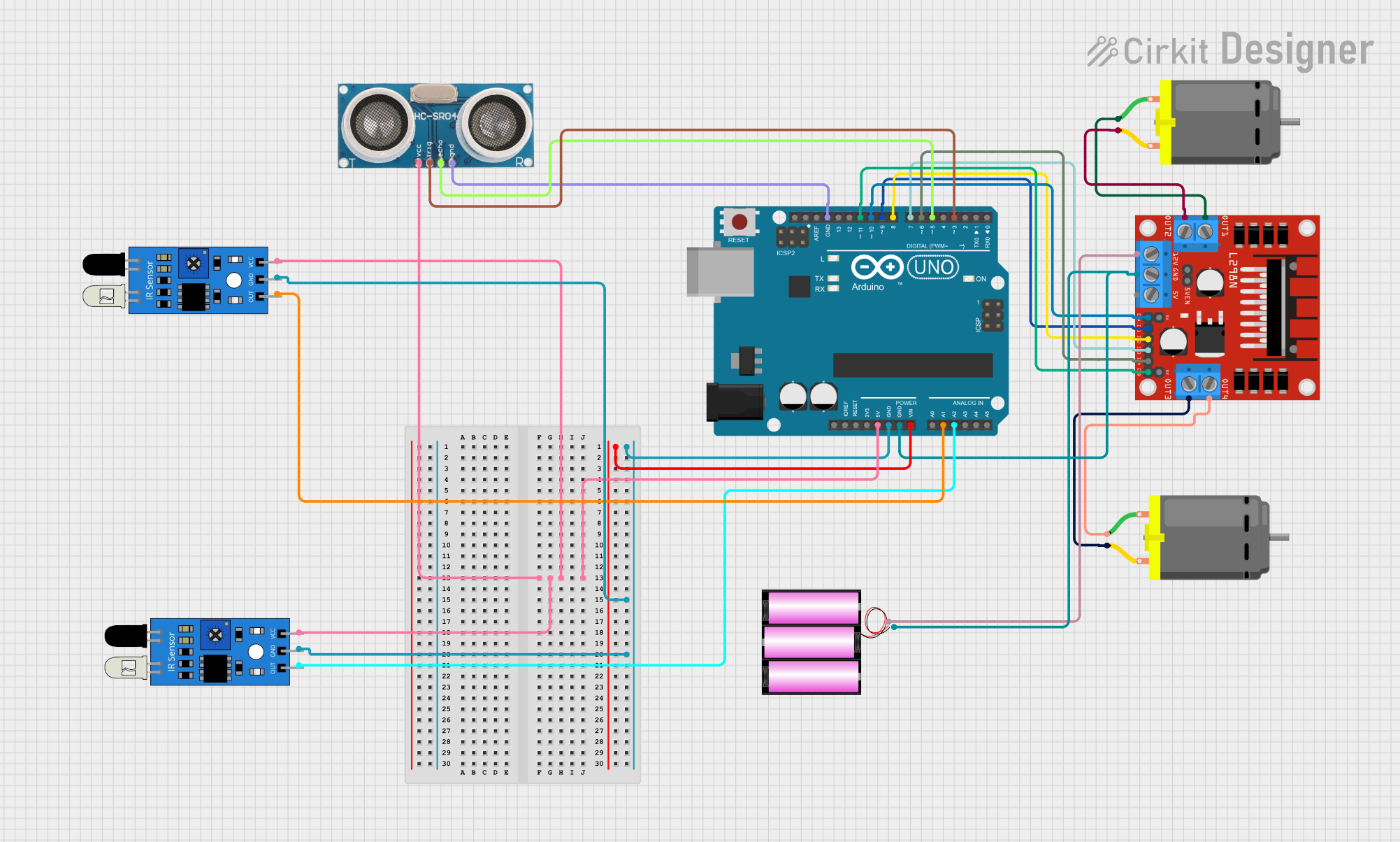
This circuit is designed to control two DC motors using an Arduino UNO microcontroller and an L298N DC motor driver. It also includes two IR sensors and an ultrasonic sensor for input, which can be used for tasks such as obstacle detection or distance measurement. The circuit is powered by a 12V battery, which also supplies power to the motor driver. The Arduino UNO regulates the power for the IR sensors and the ultrasonic sensor.
Component List
Arduino UNO
- Microcontroller board based on the ATmega328P
- It has 14 digital input/output pins, 6 analog inputs, a 16 MHz quartz crystal, a USB connection, a power jack, an ICSP header, and a reset button.
DC Motor (x2)
- An electric motor that runs on direct current (DC) electricity.
- Typically used for driving mechanical loads.
L298N DC Motor Driver
- A high-power motor driver capable of driving two DC motors.
- It has two H-bridge circuits to allow for direction control of the two motors.
12V Battery
- Provides the power source for the circuit, particularly for the motor driver and motors.
Ultrasonic Sensor
- Measures distance by emitting ultrasonic waves and measuring the time taken for the echo to return.
- Typically used in robotics for obstacle avoidance or distance measurement.
IR Sensor (x2)
- An infrared sensor that can detect obstacles or measure proximity.
- Useful for simple object detection tasks.
Wiring Details
Arduino UNO
- 5V pin provides power to both IR sensors and the ultrasonic sensor.
- GND pins are connected to the ground pins of the IR sensors, ultrasonic sensor, L298N motor driver, and the negative terminal of the battery.
- A1 pin is connected to the output of the first IR sensor.
- A2 pin is connected to the output of the second IR sensor.
- D3 pin is connected to the trigger pin of the ultrasonic sensor.
- D5 pin is connected to the echo pin of the ultrasonic sensor.
- D6-D11 pins are connected to the input and enable pins of the L298N motor driver to control the motors.
DC Motors
- Each motor has two pins connected to the output pins of the L298N motor driver, allowing for control of the motor's speed and direction.
L298N DC Motor Driver
- GND pin is connected to the ground of the circuit.
- 12V pin is connected to the positive terminal of the battery to power the motors.
- ENA and ENB pins are connected to the Arduino for enabling the motor outputs.
- IN1-IN4 pins are connected to the Arduino to control the direction of the motors.
- OUT1-OUT4 pins are connected to the DC motors.
12V Battery
- + terminal is connected to the 12V input of the L298N motor driver.
- - terminal is connected to the ground of the circuit.
Ultrasonic Sensor
- +VCC pin is powered by the 5V output from the Arduino.
- GND pin is connected to the ground of the circuit.
- Trigger pin is connected to the D3 pin on the Arduino.
- Echo pin is connected to the D5 pin on the Arduino.
IR Sensors
- VCC pins are powered by the 5V output from the Arduino.
- GND pins are connected to the ground of the circuit.
- Out pins are connected to the A1 and A2 pins on the Arduino.
Documented Code
Arduino UNO Code (sketch.ino)
void setup() {
  // put your setup code here, to run once:

}

void loop() {
  // put your main code here, to run repeatedly:

}
Note: The provided code is a template and does not include specific functionality. It should be populated with the setup and loop functions to initialize the pins and implement the control logic for the sensors and motor driver.