
ESP32-Based Room AC Control System with HTU21D-F Sensors and OLED Display
View and Edit Project In Cirkit Designer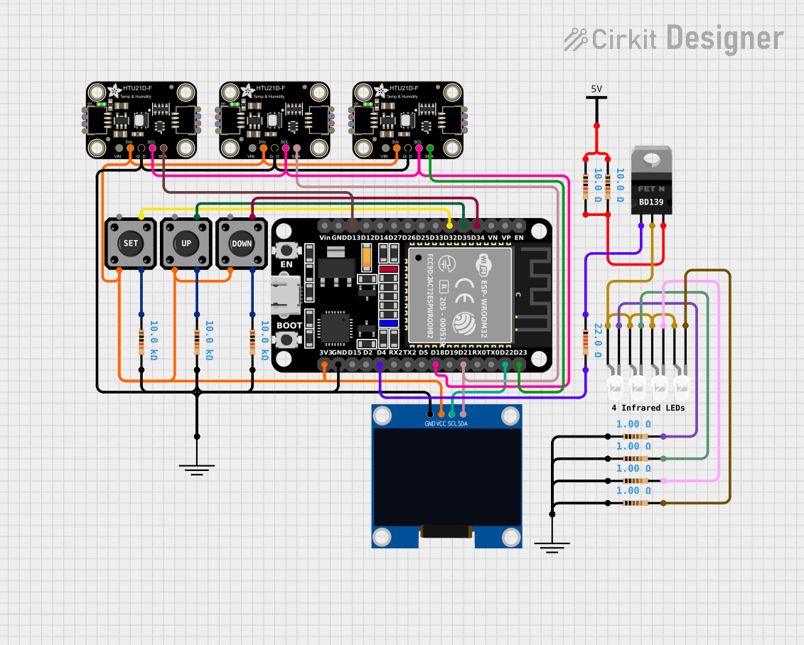
Circuit Documentation
Summary
The circuit is designed to control a room air conditioner using an ESP32 microcontroller. It features three tactile switch buttons for user input to set and adjust the temperature. The circuit also includes three Adafruit HTU21D-F temperature and humidity sensors for environmental monitoring. An OLED display is used to show the current temperature, humidity, and set temperature. The circuit controls four LEDs, which are presumably used to send signals to the air conditioner. The ESP32 microcontroller is programmed to read sensor data, manage user inputs, and control the LEDs based on the temperature settings.
Component List
Tactile Switch Buttons - 12mm Square
- Description: Pushbutton switches for user input.
- Pins: 3, 1, 4, 2
Resistor (10k Ohms)
- Description: Resistors used for pull-up/down configurations or current limiting.
- Resistance: 10k Ohms
Resistor (22 Ohms)
- Description: Current limiting resistor for the MOSFET gate.
- Resistance: 22 Ohms
Resistor (10 Ohms)
- Description: Current limiting resistors for the LEDs.
- Resistance: 10 Ohms
Resistor (1 Ohm)
- Description: Current limiting resistors, possibly for power distribution or LED current balancing.
- Resistance: 1 Ohm
GND
- Description: Ground reference for the circuit.
nMOS Transistor (MOSFET)
- Description: MOSFET used as a switch to control the LEDs.
- Pins: Gate, Drain, Source
ESP32 (30 pin)
- Description: Microcontroller used for controlling the circuit logic.
- Pins: EN, VP, VN, D34, D35, D32, D33, D25, D26, D27, D14, D12, D13, GND, Vin, D23, D22, TX0, RX0, D21, D19, D18, D5, TX2, RX2, D4, D2, D15, 3V3
Adafruit HTU21D-F Temperature & Humidity Sensor
- Description: Sensors for measuring temperature and humidity.
- Pins: VCC, 3.3V, GND, SCL, SDA
Vcc
- Description: Power supply for the circuit.
LED: Two Pin (white)
- Description: LEDs used for signaling.
- Pins: Cathode, Anode
128x64 OLED Display (I2C IIC SPI Serial)
- Description: Display for showing temperature, humidity, and set temperature.
- Pins: GND, SDA, SCL, VCC
Wiring Details
Tactile Switch Buttons - 12mm Square
- Pin 2: Connected to ESP32 D34, D35, D32 for button input.
- Pin 3: Connected to 3.3V power rail.
- Pin 4: Connected to 10k Ohm resistors to GND.
Resistor (10k Ohms)
- Pin 1: Connected to tactile switch pin 4.
- Pin 2: Connected to GND.
Resistor (22 Ohms)
- Pin 1: Connected to ESP32 D4.
- Pin 2: Connected to MOSFET gate.
Resistor (10 Ohms)
- Pin 1: Connected to Vcc.
- Pin 2: Connected to LED anodes and MOSFET source.
Resistor (1 Ohm)
- Pin 1: Connected to LED cathodes.
- Pin 2: Connected to GND.
nMOS Transistor (MOSFET)
- Gate: Connected to 22 Ohm resistor to ESP32 D4.
- Drain: Connected to LED anodes.
- Source: Connected to 10 Ohm resistors to Vcc.
ESP32 (30 pin)
- D34, D35, D32: Connected to tactile switch buttons.
- D13, D23, D21, D18: Connected to SDA and SCL of the OLED display and HTU21D-F sensors.
- GND: Connected to GND.
- 3V3: Connected to 3.3V power rail.
Adafruit HTU21D-F Temperature & Humidity Sensor
- SDA: Connected to ESP32 D13, D23, D21 and OLED display SDA.
- SCL: Connected to ESP32 D18 and OLED display SCL.
- GND: Connected to GND.
- 3.3V: Connected to 3.3V power rail.
LED: Two Pin (white)
- Anode: Connected to MOSFET drain and 10 Ohm resistors.
- Cathode: Connected to 1 Ohm resistors to GND.
128x64 OLED Display (I2C IIC SPI Serial)
- SDA: Connected to ESP32 D13, D23, D21 and HTU21D-F sensors SDA.
- SCL: Connected to ESP32 D18 and HTU21D-F sensors SCL.
- GND: Connected to GND.
- VCC: Connected to 3.3V power rail.
Documented Code
/*
 * Room AC Control Project
 *
 * This project is designed to control a room air conditioner using an ESP32 microcontroller.
 * The system includes three pushbuttons for setting the temperature, increasing, and decreasing the set temperature.
 * It also includes three HTU21D-F temperature and humidity sensors to monitor the room environment.
 * An OLED display is used to show the current temperature, humidity, and set temperature.
 * Four infrared LEDs are used to send control signals to the air conditioner.
 */

#include <Wire.h>
#include <Adafruit_Sensor.h>
#include <Adafruit_HTU21DF.h>
#include <Adafruit_GFX.h>
#include <Adafruit_SSD1306.h>

// Pin definitions
#define SET_BUTTON_PIN 32
#define UP_BUTTON_PIN 35
#define DOWN_BUTTON_PIN 34
#define LED_PIN 4

// OLED display dimensions
#define SCREEN_WIDTH 128
#define SCREEN_HEIGHT 64

// Create instances for the sensors and display
Adafruit_HTU21DF htu1 = Adafruit_HTU21DF();
Adafruit_HTU21DF htu2 = Adafruit_HTU21DF();
Adafruit_HTU21DF htu3 = Adafruit_HTU21DF();
Adafruit_SSD1306 display(SCREEN_WIDTH, SCREEN_HEIGHT, &Wire, -1);

// Variables to store temperature settings
float setTemperature = 24.0; // Default set temperature
float currentTemperature = 0.0;
float currentHumidity = 0.0;

void setup() {
  // Initialize serial communication
  Serial.begin(115200);

  // Initialize the pushbutton pins
  pinMode(SET_BUTTON_PIN, INPUT_PULLUP);
  pinMode(UP_BUTTON_PIN, INPUT_PULLUP);
  pinMode(DOWN_BUTTON_PIN, INPUT_PULLUP);

  // Initialize the LED pin
  pinMode(LED_PIN, OUTPUT);

  // Initialize the sensors
  if (!htu1.begin() || !htu2.begin() || !htu3.begin()) {
    Serial.println("Couldn't find HTU21D-F sensor!");
    while (1);
  }

  // Initialize the OLED display
  if (!display.begin(SSD1306_SWITCHCAPVCC, 0x3C)) {
    Serial.println("SSD1306 allocation failed");
    for (;;);
  }
  display.display();
  delay(2000); // Pause for 2 seconds
  display.clearDisplay();
}

void loop() {
  // Read the pushbutton states
  bool setButtonPressed = !digitalRead(SET_BUTTON_PIN);
  bool upButtonPressed = !digitalRead(UP_BUTTON_PIN);
  bool downButtonPressed = !digitalRead(DOWN_BUTTON_PIN);

  // Adjust the set temperature based on button presses
  if (upButtonPressed) {
    setTemperature += 0.5;
  }
  if (downButtonPressed) {
    setTemperature -= 0.5;
  }

  // Read the sensor data
  currentTemperature = (htu1.readTemperature() + htu2.readTemperature() + htu3.readTemperature()) / 3.0;
  currentHumidity = (htu1.readHumidity() + htu2.readHumidity() + htu3.readHumidity()) / 3.0;

  // Update the OLED display
  display.clearDisplay();
  display.setTextSize(1);
  display.setTextColor(SSD1306_WHITE);
  display.setCursor(0, 0);
  display.print("Set Temp: ");
  display.print(setTemperature);
  display.print(" C");
  display.setCursor(0, 10);
  display.print("Current Temp: ");
  display.print(currentTemperature);
  display.print(" C");
  display.setCursor(0, 20);
  display.print("Humidity: ");
  display.print(currentHumidity);
  display.print(" %");
  display.display();

  // Control the LED based on the set temperature
  if (currentTemperature > setTemperature) {
    digitalWrite(LED_PIN, HIGH); // Turn on the LED
  } else {
    digitalWrite(LED_PIN, LOW); // Turn off the LED
  }

  // Small delay to debounce buttons
  delay(200);
}
This code is responsible for the operation of the ESP32 microcontroller within the circuit. It initializes the hardware components, reads sensor data