Bluetooth-Controlled Smart Lighting System with Arduino and Relay
Circuit Documentation
Summary
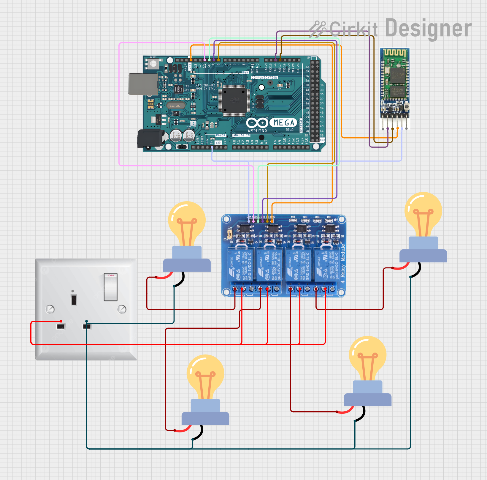
The circuit in question is designed to control multiple AC-powered LED bulbs using an Arduino Mega 2560 microcontroller and a 4-channel 5V relay module. The system also includes a Bluetooth module for potential wireless control capabilities. The AC wall plug point provides the main power source for the LED bulbs, while the Arduino Mega 2560 and the relay module operate at low voltage DC power supplied by the same Arduino board. The relay module acts as an intermediary, allowing the microcontroller to safely control the high-voltage AC bulbs.
Component List
LED Bulb AC / Bombillo AC
- Description: A standard LED bulb designed for AC operation.
- Pins:
+(positive),-(negative)
Relay 4 Channel 5v
- Description: A 4-channel relay module that allows for controlling up to four separate high-power devices.
- Pins:
GND,IN1,IN2,IN3,IN4,VCC,COM1,COM2,COM3,COM4,NO1,NO2,NO3,NO4,NC1,NC2,NC3,NC4
Arduino Mega 2560
- Description: A microcontroller board based on the ATmega2560, with a wide range of input/output options.
- Pins: Multiple digital and analog pins, including
GND,5V,D8 PWM,D9 PWM,D10 PWM,D11 PWM,D17 PWM/RX2,D16 PWM/TX2, and others.
Bluetooth Module
- Description: A Bluetooth interface module for wireless communication.
- Pins:
en,vcc,gnd,txd,rxd,start
AC Wall Plug Point
- Description: A standard wall plug point for AC power supply.
- Pins:
E(Earth),N(Neutral),L(Live)
Wiring Details
LED Bulb AC / Bombillo AC
- Positive Pin (
+): Connected to the Normally Open (NO) pin of the corresponding channel on the relay module. - Negative Pin (
-): Commonly connected to the Live (L) pin of the AC wall plug point.
Relay 4 Channel 5v
- Ground (GND): Connected to the GND pin of the Arduino Mega 2560 and the GND pin of the Bluetooth module.
- Input Pins (IN1, IN2, IN3, IN4): Each connected to a corresponding PWM-capable digital pin on the Arduino Mega 2560 (D8, D9, D10, D11).
- VCC: Connected to the 5V pin of the Arduino Mega 2560 and the VCC pin of the Bluetooth module.
- Common Pins (COM1, COM2, COM3, COM4): All connected to the Neutral (N) pin of the AC wall plug point.
- Normally Open Pins (NO1, NO2, NO3, NO4): Each connected to the positive pin of a corresponding LED bulb.
Arduino Mega 2560
- Ground (GND): Connected to the GND pin of the Bluetooth module and the GND pin of the relay module.
- 5V: Connected to the VCC pin of the Bluetooth module and the VCC pin of the relay module.
- Digital Pins (D8, D9, D10, D11): Each connected to a corresponding input pin on the relay module (IN1, IN2, IN3, IN4).
- Digital Pins (D17 PWM/RX2, D16 PWM/TX2): Connected to the TXD and RXD pins of the Bluetooth module, respectively.
Bluetooth Module
- Ground (GND): Connected to the GND pin of the Arduino Mega 2560.
- VCC: Connected to the 5V pin of the Arduino Mega 2560.
- TXD: Connected to the RX2 pin (D17) of the Arduino Mega 2560.
- RXD: Connected to the TX2 pin (D16) of the Arduino Mega 2560.
AC Wall Plug Point
- Neutral (N): Connected to the common pins of the relay module (COM1, COM2, COM3, COM4).
- Live (L): Connected to the negative pins of all LED bulbs.
Documented Code
Arduino Mega 2560 Code (sketch.ino)
void setup() {
  // put your setup code here, to run once:

}

void loop() {
  // put your main code here, to run repeatedly:

}
This code is a template and does not contain any functional instructions. The setup() function is intended to contain initialization code that runs once when the microcontroller is powered on or reset. The loop() function is intended to contain the main logic of the program, which runs repeatedly as long as the microcontroller is powered.
Additional Notes
- The Bluetooth module is intended for wireless communication, but the specific implementation details are not provided in the code snippet.
- The relay module is controlled by the Arduino Mega 2560, but the code to operate the relays is not included in the provided snippet.
- The AC wall plug point provides the main power for the LED bulbs, which are switched on and off by the relay module under the control of the Arduino Mega 2560.