
ESP32-Based Battery-Powered Load Cell Weight Measurement System with LCD Display
View and Edit Project In Cirkit Designer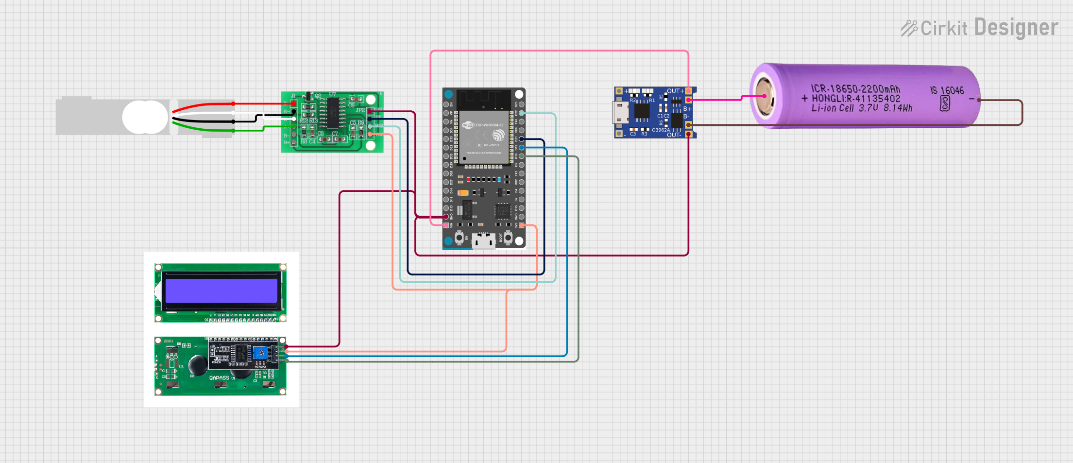
Circuit Documentation
Summary
This document provides a detailed overview of a circuit that includes a load cell, an HX711 bridge sensor interface, an ESP32 Devkit V1, an LCD with I2C interface, a TP4056 battery charger, and a 18650 battery. The circuit is designed to measure weight using the load cell, process the data with the HX711 and ESP32, and display the results on the LCD. The TP4056 is used to charge the 18650 battery, which powers the entire circuit.
Component List
HX711 - Bridge Sensor Interface
- Description: Interface for load cells to measure weight.
- Pins: E+, E-, A-, A+, B-, B+, GND - GROUND, DATA (OUT), SCK - CLOCK (IN), 3.3/3.5V Supply
lcdi2c
- Description: LCD display with I2C interface.
- Pins: GND, VCC, SDA, SCL
TP4056
- Description: Lithium-ion battery charger.
- Pins: OUT-, B-, B+, OUT+, IN-, IN+
Load Cell - Red/white/black/green
- Description: Sensor to measure weight.
- Pins: E+, A-, E-, A+
ESP32 Devkit V1
- Description: Microcontroller with Wi-Fi and Bluetooth capabilities.
- Pins: 3V3, GND, D15, D2, D4, RX2, TX2, D5, D18, D19, D21, RX0, TX0, D22, D23, EN, VP, VN, D34, D35, D32, D33, D25, D26, D27, D14, D12, D13, VIN
Battery 18650
- Description: Rechargeable lithium-ion battery.
- Pins: +, -
Wiring Details
HX711 - Bridge Sensor Interface
- E+ connected to Load Cell - Red/white/black/green E+
- A- connected to Load Cell - Red/white/black/green A-
- E- connected to Load Cell - Red/white/black/green E-
- A+ connected to Load Cell - Red/white/black/green A+
- GND - GROUND connected to ESP32 Devkit V1 GND, lcdi2c GND, TP4056 OUT-
- DATA (OUT) connected to ESP32 Devkit V1 D21
- SCK - CLOCK (IN) connected to ESP32 Devkit V1 D22
- 3.3/3.5V Supply connected to ESP32 Devkit V1 3V3, lcdi2c VCC
lcdi2c
- GND connected to ESP32 Devkit V1 GND, HX711 - Bridge Sensor Interface GND - GROUND, TP4056 OUT-
- VCC connected to ESP32 Devkit V1 3V3, HX711 - Bridge Sensor Interface 3.3/3.5V Supply
- SDA connected to ESP32 Devkit V1 D19
- SCL connected to ESP32 Devkit V1 D18
TP4056
- OUT- connected to ESP32 Devkit V1 GND, lcdi2c GND, HX711 - Bridge Sensor Interface GND - GROUND
- B- connected to Battery 18650 -
- B+ connected to Battery 18650 +
- OUT+ connected to ESP32 Devkit V1 VIN
Load Cell - Red/white/black/green
- E+ connected to HX711 - Bridge Sensor Interface E+
- A- connected to HX711 - Bridge Sensor Interface A-
- E- connected to HX711 - Bridge Sensor Interface E-
- A+ connected to HX711 - Bridge Sensor Interface A+
ESP32 Devkit V1
- GND connected to lcdi2c GND, HX711 - Bridge Sensor Interface GND - GROUND, TP4056 OUT-
- D21 connected to HX711 - Bridge Sensor Interface DATA (OUT)
- D22 connected to HX711 - Bridge Sensor Interface SCK - CLOCK (IN)
- 3V3 connected to lcdi2c VCC, HX711 - Bridge Sensor Interface 3.3/3.5V Supply
- VIN connected to TP4056 OUT+
- D19 connected to lcdi2c SDA
- D18 connected to lcdi2c SCL
Battery 18650
- - connected to TP4056 B-
- + connected to TP4056 B+
Code
No code is provided for this circuit.
This document provides a comprehensive overview of the circuit, including a summary, component list, wiring details, and code section. The wiring details ensure that each component is correctly connected to the others, facilitating the proper functioning of the circuit.