
ESP8266 NodeMCU Controlled Smart Irrigation System with Soil Moisture Sensing and DHT11 Feedback
View and Edit Project In Cirkit Designer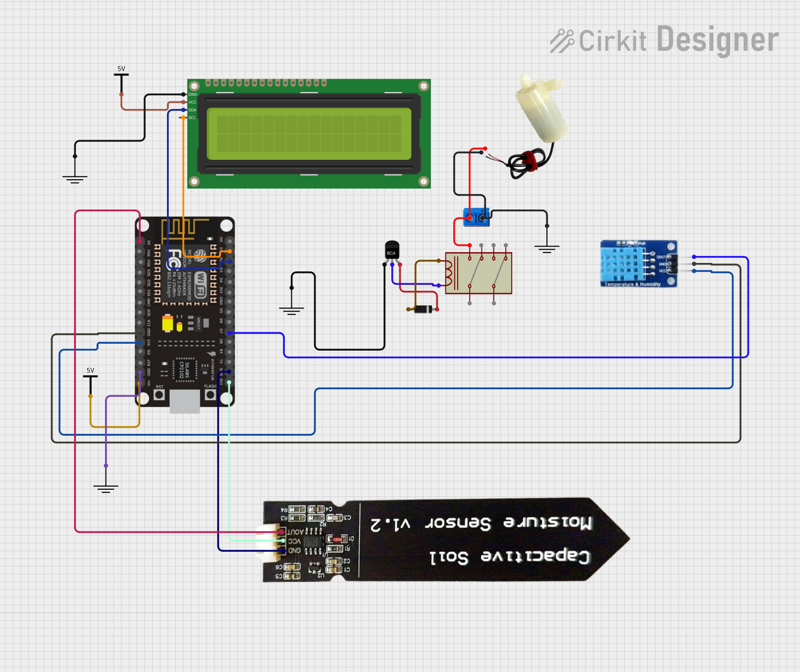
Circuit Documentation
Summary
This circuit is designed to monitor soil moisture levels and control a water pump based on the moisture data. It uses an ESP8266 NodeMCU microcontroller to read data from a capacitive soil moisture sensor and a DHT11 temperature and humidity sensor. The microcontroller processes the data and controls a relay that switches a 5V mini water pump on or off. The system also includes a 16x2 I2C LCD display to show the moisture, temperature, and humidity readings. The circuit is powered by a 3.3V supply from the ESP8266 NodeMCU, and the relay is driven by an NPN transistor and a diode for protection.
Component List
- Diode: A semiconductor device that allows current to flow in one direction only, used here for protection in the relay circuit.
- Relay: An electrically operated switch that uses an electromagnet to mechanically operate a switch, used to control the water pump.
- Capacitive Soil Moisture Sensor V1.2: A sensor that measures the moisture level in the soil by detecting the dielectric constant of the soil.
- ESP8266 NodeMCU: A microcontroller board with Wi-Fi capability, used for reading sensors and controlling the relay.
- DHT11: A sensor that measures ambient temperature and humidity.
- NPN Transistor: A type of bipolar junction transistor used as a switch or amplifier, here used to drive the relay coil.
- GND: Ground reference for the circuit.
- 5V Mini Water Pump: A pump that moves water when powered, controlled by the relay.
- Terminal PCB 2 Pin: A simple two-pin terminal block for making easy connections to the board.
- 16x2 I2C LCD: A liquid crystal display that can show 16 characters per line on 2 lines, used for displaying sensor data.
- Vcc: The power supply for the circuit components.
Wiring Details
Diode
- Cathode connected to the base of the NPN transistor.
- Anode connected to the coil of the relay.
Relay
- Common 1 and Common 2 are not connected in this circuit.
- Coil connected to the anode of the diode and collector of the NPN transistor.
- NO 1 (Normally Open) connected to the positive pin of the water pump.
- NC 1 (Normally Closed) is not connected in this circuit.
- NO 2 and NC 2 are not connected in this circuit.
Capacitive Soil Moisture Sensor V1.2
- GND connected to the GND of the ESP8266 NodeMCU.
- VCC connected to the 3V3 output of the ESP8266 NodeMCU.
- AOUT connected to the A0 analog input of the ESP8266 NodeMCU.
ESP8266 NodeMCU
- GND connected to the GND of the soil moisture sensor, DHT11, 16x2 I2C LCD, and the emitter of the NPN transistor.
- 3V3 connected to the VCC of the soil moisture sensor and DHT11.
- A0 connected to the AOUT of the soil moisture sensor.
- D7 connected to the DATA pin of the DHT11.
- D1 connected to the SCL pin of the 16x2 I2C LCD.
- D2 connected to the SDA pin of the 16x2 I2C LCD.
- VIN connected to the Vcc power supply.
DHT11
- DATA connected to the D7 of the ESP8266 NodeMCU.
- GND connected to the GND of the ESP8266 NodeMCU.
- VCC connected to the 3V3 of the ESP8266 NodeMCU.
NPN Transistor
- E (Emitter) connected to the GND.
- C (Collector) connected to the coil of the relay.
- B (Base) connected to the cathode of the diode.
5V Mini Water Pump
- Positive pin connected to the NO 1 of the relay.
- Negative pin connected to the GND.
Terminal PCB 2 Pin
- Pin A connected to the positive pin of the water pump.
- Pin B connected to the negative pin of the water pump.
16x2 I2C LCD
- GND connected to the GND of the ESP8266 NodeMCU.
- VCC connected to the Vcc power supply.
- SDA connected to the D2 of the ESP8266 NodeMCU.
- SCL connected to the D1 of the ESP8266 NodeMCU.
Documented Code
#define BLYNK_TEMPLATE_ID "TMPL36RX0P6rk"
#define BLYNK_TEMPLATE_NAME "PROJECT5"
#define BLYNK_AUTH_TOKEN "5YkIXWTwTpnhqS3O2XBt577msEFR1KU2"
#include <Wire.h>
#include <LiquidCrystal_I2C.h>
#include <DHT.h>
#include <ESP8266WiFi.h>
#include <BlynkSimpleEsp8266.h>

LiquidCrystal_I2C lcd(0x27, 16, 2);
char ssid[]="Redmi 9";
char password[]="11111111";
const float referenceResistor = 10000.0;
const float betaCoefficient = 3950.0;
const float nominalResistance = 10000.0;
const int adcMaxValue = 1023;
#define DHTPIN D7
#define soilpin A0
#define DHTTYPE DHT11
#define MOTOR_PIN D3

DHT dht(DHTPIN, DHTTYPE);

void setup() {
  Serial.begin(115200);
  lcd.init();
  lcd.backlight();
  dht.begin();
  pinMode(soilpin, INPUT);
  pinMode(MOTOR_PIN, OUTPUT);
  Blynk.begin(BLYNK_AUTH_TOKEN,ssid,password);
}

void loop() {

  int soilvalue = analogRead(soilpin);

  float persoilvalue = map(soilvalue, 0, 1023, 0, 100);

  float temval = dht.readTemperature();
  float humval = dht.readHumidity();

  if (isnan(temval) || isnan(humval)) {
    Serial.println("Failed to read from DHT sensor!");
    return;
  }

  lcd.setCursor(0, 0);
  lcd.print("Moist: ");
  lcd.print(persoilvalue);
  lcd.print(" %");

  lcd.setCursor(0, 1);
  lcd.print("HUM: ");
  lcd.print(humval);
  lcd.print(" %");
  Blynk.virtualWrite(V4,humval);
  Blynk.virtualWrite(V1,temval);
  Blynk.virtualWrite(V3,persoilvalue);
  Blynk.run();

  Serial.print("Temp: ");
  Serial.println(temval);

  Serial.print("Humidity: ");
  Serial.println(humval);

  Serial.print("Soil Moisture: ");
  Serial.println(persoilvalue);

  if (persoilvalue < 40) {
    digitalWrite(MOTOR_PIN, HIGH);
  } else {
    digitalWrite(MOTOR_PIN, LOW);
  }

  delay(1000);
}
This code is designed to run on an ESP8266 NodeMCU microcontroller. It initializes the connected sensors and LCD, reads the soil moisture, temperature, and humidity, and displays the values on the LCD. It also sends the data to the Blynk IoT platform. If the soil moisture is below 40%, it activates the water pump by setting the MOTOR_PIN high.