
Circuit Documentation
Summary
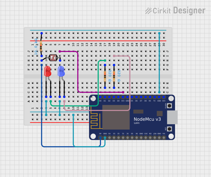
This circuit involves a NodeMCU V3 ESP8266 microcontroller, two LEDs (one red and one blue), a photocell (LDR), and three resistors. The circuit is designed to read the light intensity using the photocell and control the LEDs accordingly. The NodeMCU is programmed to handle the logic for reading the sensor data and controlling the LEDs.
Component List
NodeMCU V3 ESP8266
- Description: A microcontroller with built-in Wi-Fi capabilities.
- Pins: A0, GND, VU, S3, S2, S1, SC, S0, SK, 3V3, EN, RST, Vin, D0, D1, D2, D3, D4, D5, D6, D7, D8, RX, TX
LED: Two Pin (red)
- Description: A red LED with two pins.
- Pins: cathode, anode
LED: Two Pin (blue)
- Description: A blue LED with two pins.
- Pins: cathode, anode
Photocell (LDR)
- Description: A light-dependent resistor used to measure light intensity.
- Pins: pin 0, pin 1
Resistor (10k Ohms)
- Description: A resistor with a resistance of 10k Ohms.
- Pins: pin1, pin2
Resistor (320 Ohms)
- Description: A resistor with a resistance of 320 Ohms.
- Pins: pin1, pin2
Resistor (320 Ohms)
- Description: A resistor with a resistance of 320 Ohms.
- Pins: pin1, pin2
Wiring Details
NodeMCU V3 ESP8266
- A0: Connected to pin 1 of the 10k Ohm resistor and pin 0 of the photocell.
- GND: Connected to the cathode of the red LED, the cathode of the blue LED, and pin 2 of the 10k Ohm resistor.
- 3V3: Connected to pin 1 of the photocell.
- D1: Connected to pin 2 of the 320 Ohm resistor (connected to the red LED).
- D3: Connected to pin 2 of the 320 Ohm resistor (connected to the blue LED).
LED: Two Pin (red)
- cathode: Connected to GND of the NodeMCU.
- anode: Connected to pin 1 of the 320 Ohm resistor.
LED: Two Pin (blue)
- cathode: Connected to GND of the NodeMCU.
- anode: Connected to pin 1 of the 320 Ohm resistor.
Photocell (LDR)
- pin 0: Connected to pin 1 of the 10k Ohm resistor and A0 of the NodeMCU.
- pin 1: Connected to 3V3 of the NodeMCU.
Resistor (10k Ohms)
- pin1: Connected to pin 0 of the photocell and A0 of the NodeMCU.
- pin2: Connected to GND of the NodeMCU.
Resistor (320 Ohms)
- pin1: Connected to the anode of the red LED.
- pin2: Connected to D1 of the NodeMCU.
Resistor (320 Ohms)
- pin1: Connected to the anode of the blue LED.
- pin2: Connected to D3 of the NodeMCU.
Code Documentation
sketch.ino
void setup() {
  // put your setup code here, to run once:

}

void loop() {
  // put your main code here, to run repeatedly:

}
documentation.txt