
Circuit Documentation
Summary
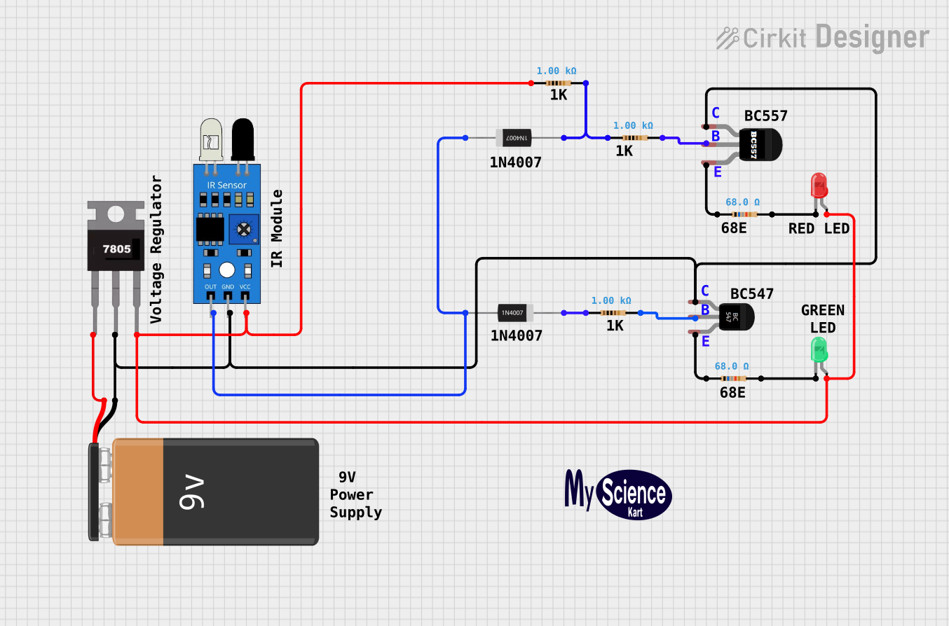
The circuit described by the provided inputs is a power supply and sensor circuit with indication LEDs. It includes a 9V battery connected to a 7805 voltage regulator to provide a stable 5V output. This 5V output powers an infrared (IR) sensor and two LEDs (one red and one green) through current-limiting resistors. The IR sensor output is conditioned by a pair of 1N4007 diodes and a BC547 transistor. A BC557 transistor is also included, which appears to be part of a switching or amplification stage.
Component List
- 9V Battery: Provides the primary power source for the circuit.
- 7805 Voltage Regulator: Regulates the input voltage to a stable 5V output.
- IR Sensor: Detects infrared signals and provides an output signal.
- 1N4007 Rectifier Diode (x2): Used for signal conditioning or protection.
- Resistor (1k Ohms x3): Current-limiting resistors for the IR sensor and LEDs.
- Resistor (68 Ohms x2): Current-limiting resistors, possibly for the transistors' base or emitter.
- BC547 Transistor: NPN transistor used for switching or amplifying signals.
- BC557 Transistor: PNP transistor used for switching or amplifying signals.
- LED (Green): Indicates the status or provides a visual output.
- LED (Red): Indicates the status or provides a visual output.
Wiring Details
9V Battery
- Negative terminal connected to the ground net.
- Positive terminal connected to the input of the 7805 voltage regulator.
7805 Voltage Regulator
- Vin: Connected to the positive terminal of the 9V battery.
- Gnd: Common ground with the IR sensor, BC547 transistor, BC557 transistor, and the negative terminal of the 9V battery.
- Vout: Provides 5V to the IR sensor, red LED, and green LED.
IR Sensor
- Vcc: Connected to the 5V output from the 7805 voltage regulator.
- Gnd: Connected to the common ground net.
- Out: Output connected to the anode of the first 1N4007 diode.
1N4007 Rectifier Diode (x2)
- First diode anode connected to the IR sensor output, cathode connected to a 1k Ohm resistor.
- Second diode cathode connected to the cathode of the first diode, anode connected to another 1k Ohm resistor.
Resistor (1k Ohms x3)
- First resistor connected between the cathode of the first 1N4007 diode and the base of the BC547 transistor.
- Second resistor connected between the anode of the second 1N4007 diode and the base of the BC557 transistor.
- Third resistor connected to the Vout of the 7805 voltage regulator and shared by the anodes of both LEDs.
Resistor (68 Ohms x2)
- First 68 Ohm resistor connected between the emitter of the BC547 transistor and ground.
- Second 68 Ohm resistor connected between the emitter of the BC557 transistor and ground.
BC547 Transistor
- Collector: Connected to the common ground net.
- Base: Connected to the cathode of the first 1N4007 diode through a 1k Ohm resistor.
- Emitter: Connected to a 68 Ohm resistor to ground.
BC557 Transistor
- Collector: Connected to the common ground net.
- Base: Connected to the anode of the second 1N4007 diode through a 1k Ohm resistor.
- Emitter: Connected to a 68 Ohm resistor to ground.
LED (Green)
- Anode: Connected to the 5V output from the 7805 voltage regulator through a 1k Ohm resistor.
- Cathode: Connected to ground through a 68 Ohm resistor.
LED (Red)
- Anode: Connected to the 5V output from the 7805 voltage regulator through a 1k Ohm resistor.
- Cathode: Connected to ground through a 68 Ohm resistor.
Documented Code
No code was provided for any microcontrollers in the circuit. If there are microcontrollers or programmable devices in the circuit, their code would be documented in this section.