
ESP32 and TB6600/TB660 Stepper Motor Driver Joystick-Controlled Dual Stepper Motor System
View and Edit Project In Cirkit Designer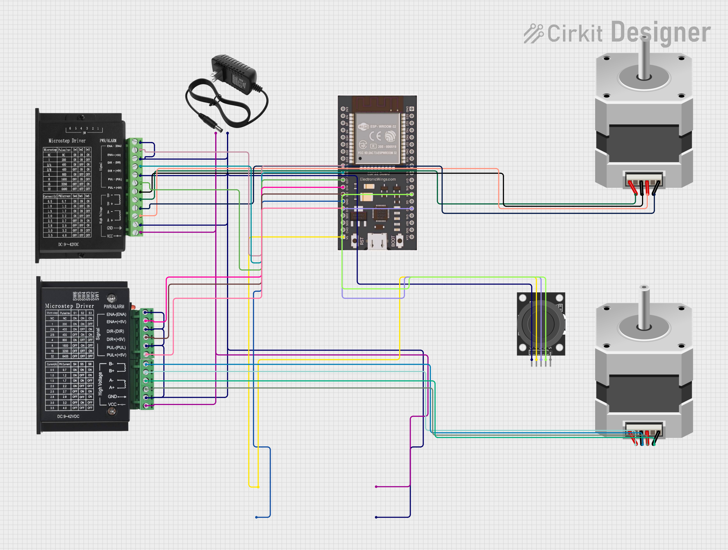
Circuit Documentation
Summary
This circuit is designed to control two stepper motors using TB6600 and TB660 stepper motor drivers, and read inputs from a KY-023 Dual Axis Joystick Module. The ESP32 microcontroller is used to interface with these components. The circuit includes a 12V power supply and a Step Up Boost Power Converter to provide the necessary voltages.
Component List
TB660 Stepper Motor Driver
- Description: Stepper motor driver for controlling stepper motors.
- Pins: ENA - (ENA), ENA+ (+5V), DIR - (DIR), DIR+ (+5V), PUL - (PUL), VCC, GND, A+, A-, B+, B-, PUL+ (+5V)
ESP32
- Description: Microcontroller used to interface with the stepper motor drivers and joystick module.
- Pins: V5, CMD, SD3, SD2, G13, GND, G12, G14, G27, G26, G25, G33, G32, G35, G34, SN, SP, EN, 3V3, G23, G22, TXD, RXD, G21, G19, G18, G5, G17, G16, G4, G0, G2, G15, SD1, SD0, CLK
NEMA23
- Description: Stepper motor.
- Pins: D, B, C, A
tb6600 Micro Stepping Motor Driver
- Description: Micro stepping motor driver for controlling stepper motors.
- Pins: ENA-, ENA+, DIR-, DIR+, PUL-, PUL+, B-, B+, A-, A+, GND, VCC
KY-023 Dual Axis Joystick Module
- Description: Joystick module for providing input to the microcontroller.
- Pins: GND, +5V, VRx, VRy, SW
12V Power Supply
- Description: Power supply providing 12V.
- Pins: +, -
Step Up Boost Power Converter, Adjustable Voltage Regulator
- Description: Voltage regulator for stepping up the voltage.
- Pins: VOUT+, VOUT-, VIN+, VIN-
Wiring Details
TB660 Stepper Motor Driver
- ENA - (ENA): Connected to GND of the 12V power supply.
- ENA+ (+5V): Connected to G25 of the ESP32.
- DIR - (DIR): Connected to GND of the 12V power supply.
- DIR+ (+5V): Connected to G26 of the ESP32.
- PUL - (PUL): Connected to GND of the 12V power supply.
- PUL+ (+5V): Connected to G27 of the ESP32.
- VCC: Connected to VIN+ of the Step Up Boost Power Converter.
- GND: Connected to GND of the 12V power supply.
- A+: Connected to B of the NEMA23 stepper motor.
- A-: Connected to D of the NEMA23 stepper motor.
- B+: Connected to A of the NEMA23 stepper motor.
- B-: Connected to C of the NEMA23 stepper motor.
ESP32
- V5: Connected to +5V of the KY-023 Dual Axis Joystick Module.
- G25: Connected to ENA+ (+5V) of the TB660 Stepper Motor Driver.
- G26: Connected to DIR+ (+5V) of the TB660 Stepper Motor Driver.
- G27: Connected to PUL+ (+5V) of the TB660 Stepper Motor Driver.
- G13: Connected to PUL+ of the tb6600 Micro Stepping Motor Driver.
- G12: Connected to DIR+ of the tb6600 Micro Stepping Motor Driver.
- G14: Connected to ENA+ of the tb6600 Micro Stepping Motor Driver.
- G4: Connected to VRy of the KY-023 Dual Axis Joystick Module.
- G2: Connected to VRx of the KY-023 Dual Axis Joystick Module.
- GND: Connected to VOUT- of the Step Up Boost Power Converter.
NEMA23 (First Motor)
- D: Connected to A- of the TB660 Stepper Motor Driver.
- B: Connected to A+ of the TB660 Stepper Motor Driver.
- C: Connected to B- of the TB660 Stepper Motor Driver.
- A: Connected to B+ of the TB660 Stepper Motor Driver.
NEMA23 (Second Motor)
- D: Connected to A- of the tb6600 Micro Stepping Motor Driver.
- B: Connected to A+ of the tb6600 Micro Stepping Motor Driver.
- C: Connected to B- of the tb6600 Micro Stepping Motor Driver.
- A: Connected to B+ of the tb6600 Micro Stepping Motor Driver.
tb6600 Micro Stepping Motor Driver
- ENA-: Connected to GND of the 12V power supply.
- ENA+: Connected to G14 of the ESP32.
- DIR-: Connected to GND of the 12V power supply.
- DIR+: Connected to G12 of the ESP32.
- PUL-: Connected to GND of the 12V power supply.
- PUL+: Connected to G13 of the ESP32.
- VCC: Connected to VIN+ of the Step Up Boost Power Converter.
- GND: Connected to GND of the 12V power supply.
- A+: Connected to B of the NEMA23 stepper motor.
- A-: Connected to D of the NEMA23 stepper motor.
- B+: Connected to A of the NEMA23 stepper motor.
- B-: Connected to C of the NEMA23 stepper motor.
KY-023 Dual Axis Joystick Module
- GND: Connected to GND of the 12V power supply.
- +5V: Connected to V5 of the ESP32.
- VRx: Connected to G2 of the ESP32.
- VRy: Connected to G4 of the ESP32.
- SW: Not connected.
12V Power Supply
- +: Connected to VIN+ of the Step Up Boost Power Converter.
- -: Connected to GND of the 12V power supply.
Step Up Boost Power Converter, Adjustable Voltage Regulator
- VOUT+: Connected to +5V of the KY-023 Dual Axis Joystick Module.
- VOUT-: Connected to GND of the ESP32.
- VIN+: Connected to + of the 12V power supply.
- VIN-: Connected to GND of the 12V power supply.
Code Documentation
ESP32 Code
/*
 * This Arduino Sketch is for controlling two stepper motors using TB6600 and
 * TB660 stepper motor drivers, and reading inputs from a KY-023 Dual Axis
 * Joystick Module. The ESP32 microcontroller is used to interface with these
 * components. The code initializes the pins and provides basic functionality
 * to control the stepper motors and read the joystick inputs.
 */

// Pin definitions
const int ENA1 = 25; // TB660 ENA+ (+5V)
const int DIR1 = 26; // TB660 DIR+ (+5V)
const int PUL1 = 27; // TB660 PUL+ (+5V)
const int ENA2 = 14; // TB6600 ENA+
const int DIR2 = 12; // TB6600 DIR+
const int PUL2 = 13; // TB6600 PUL+
const int VRx = 2;   // Joystick VRx
const int VRy = 4;   // Joystick VRy

void setup() {
  // Initialize serial communication
  Serial.begin(115200);

  // Initialize stepper motor control pins
  pinMode(ENA1, OUTPUT);
  pinMode(DIR1, OUTPUT);
  pinMode(PUL1, OUTPUT);
  pinMode(ENA2, OUTPUT);
  pinMode(DIR2, OUTPUT);
  pinMode(PUL2, OUTPUT);

  // Initialize joystick input pins
  pinMode(VRx, INPUT);
  pinMode(VRy, INPUT);

  // Enable stepper motors
  digitalWrite(ENA1, HIGH);
  digitalWrite(ENA2, HIGH);
}

void loop() {
  // Read joystick values
  int xValue = analogRead(VRx);
  int yValue = analogRead(VRy);

  // Print joystick values to serial monitor
  Serial.print("Joystick X: ");
  Serial.print(xValue);
  Serial.print("\tJoystick Y: ");
  Serial.println(yValue);

  // Control stepper motors based on joystick input