
Arduino UNO-Based Smart LED Strip Controller with Battery Monitoring and SOS Alert
View and Edit Project In Cirkit Designer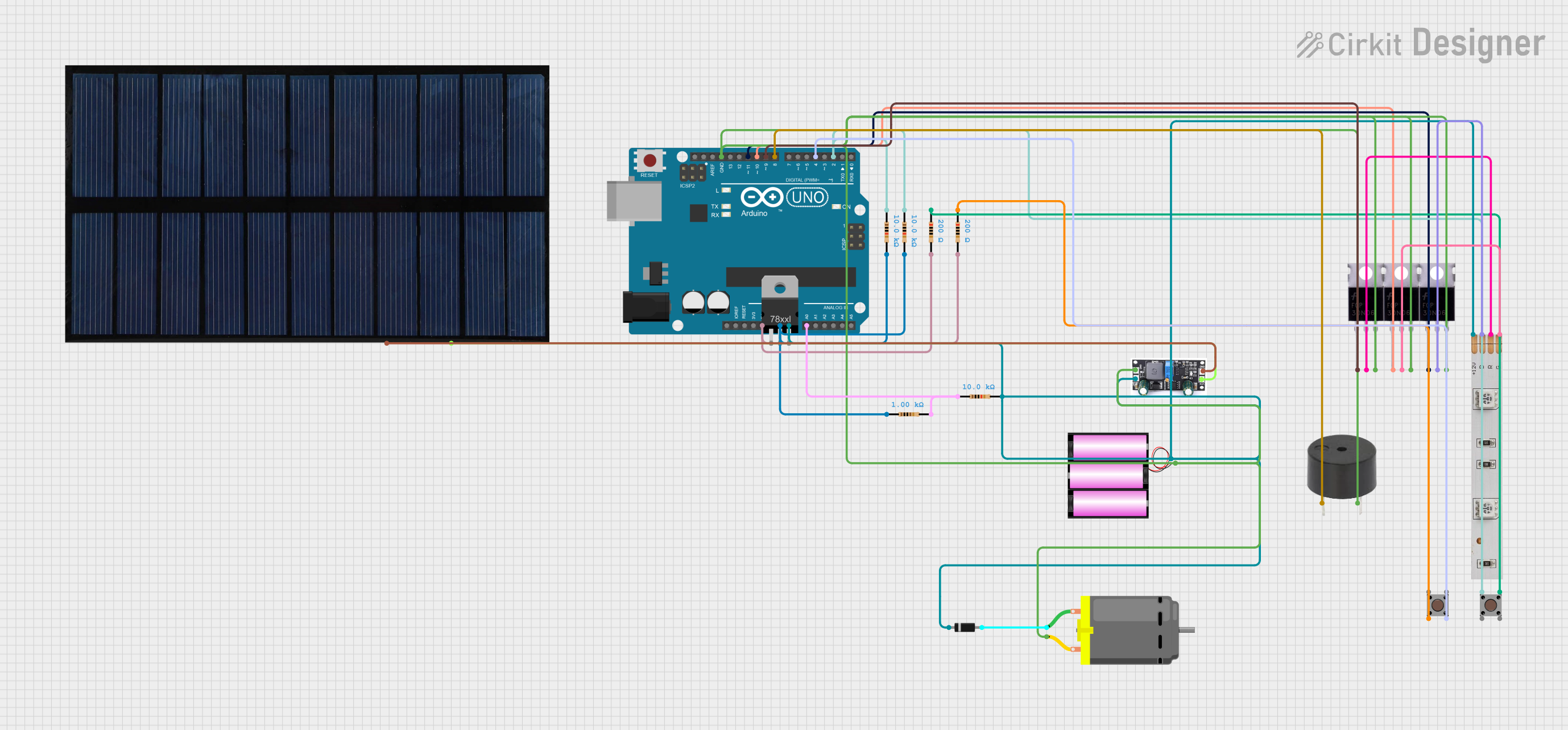
Circuit Documentation
Summary
This circuit is designed to control an LED strip, a DC motor, and a buzzer using an Arduino UNO. It also includes a battery voltage monitoring system and two pushbuttons for user interaction. The LED strip can display different colors, and the buzzer can emit an SOS signal. The circuit is powered by a 12V battery and includes a charge controller for solar charging.
Component List
Arduino UNO
- Description: Microcontroller board based on the ATmega328P.
- Pins: UNUSED, IOREF, Reset, 3.3V, 5V, GND, Vin, A0, A1, A2, A3, A4, A5, SCL, SDA, AREF, D13, D12, D11, D10, D9, D8, D7, D6, D5, D4, D3, D2, D1, D0
LED Strip
- Description: RGB LED strip.
- Pins: B, +12V, R, G
Pushbutton
- Description: Momentary pushbutton switch.
- Pins: Pin 3 (out), Pin 4 (out), Pin 1 (in), Pin 2 (in)
Resistor (10k Ohms)
- Description: Resistor with a resistance of 10k Ohms.
- Pins: pin1, pin2
Resistor (200 Ohms)
- Description: Resistor with a resistance of 200 Ohms.
- Pins: pin1, pin2
Battery 12V
- Description: 12V battery.
- Pins: +, -
Mosfet
- Description: Metal-Oxide-Semiconductor Field-Effect Transistor (MOSFET).
- Pins: Gate, Drain, Source
Charge Controller
- Description: Charge controller for solar charging.
- Pins: GND, BAT, Vin
Diode
- Description: Diode for current direction control.
- Pins: cathode, anode
Solar Cell
- Description: Solar cell for generating electricity.
- Pins: +, -
DC Motor
- Description: Direct Current (DC) motor.
- Pins: pin 1, pin 2
Buzzer
- Description: Piezoelectric buzzer.
- Pins: PIN, GND
Voltage Regulator
- Description: Voltage regulator for stabilizing voltage.
- Pins: IN, GND, OUT
Wiring Details
Arduino UNO
- 5V connected to Resistor (200 Ohms) pin2 and Resistor (200 Ohms) pin2.
- GND connected to Resistor (10k Ohms) pin2, Resistor (10k Ohms) pin2, Resistor (1k Ohms) pin1, Mosfet Source, DC Motor pin 2, Mosfet Source, Charge Controller GND, Mosfet Source, Battery 12V -, and Buzzer GND.
- Vin connected to Charge Controller BAT, Diode cathode, Battery 12V +, LED Strip +12V, and Resistor (10k Ohms) pin2.
- A0 connected to Resistor (1k Ohms) pin2 and Resistor (10k Ohms) pin1.
- D11 connected to Mosfet Gate.
- D10 connected to Mosfet Gate.
- D9 connected to Mosfet Gate.
- D8 connected to Buzzer PIN.
- D4 connected to Pushbutton Pin 4 (out).
- D2 connected to Pushbutton Pin 4 (out), Resistor (10k Ohms) pin1, and Resistor (10k Ohms) pin1.
LED Strip
- B connected to Mosfet Drain.
- R connected to Mosfet Drain.
- G connected to Mosfet Drain.
Pushbutton
- Pin 4 (out) connected to Arduino UNO D4.
- Pin 4 (out) connected to Arduino UNO D2, Resistor (10k Ohms) pin1, and Resistor (10k Ohms) pin1.
- Pin 2 (in) connected to Resistor (200 Ohms) pin1.
- Pin 2 (in) connected to Resistor (200 Ohms) pin1.
Resistor (10k Ohms)
- pin2 connected to Arduino UNO GND.
- pin2 connected to Arduino UNO GND.
- pin1 connected to Resistor (1k Ohms) pin1.
- pin2 connected to Arduino UNO Vin.
Resistor (200 Ohms)
- pin2 connected to Arduino UNO 5V.
- pin2 connected to Arduino UNO 5V.
- pin1 connected to Pushbutton Pin 2 (in).
- pin1 connected to Pushbutton Pin 2 (in).
Battery 12V
- + connected to Arduino UNO Vin, Charge Controller BAT, Diode cathode, LED Strip +12V, and Resistor (10k Ohms) pin2.
- - connected to Arduino UNO GND, Mosfet Source, DC Motor pin 2, Mosfet Source, Charge Controller GND, Mosfet Source, and Buzzer GND.
Mosfet
- Source connected to Arduino UNO GND, DC Motor pin 2, Charge Controller GND, Battery 12V -, and Buzzer GND.
- Gate connected to Arduino UNO D11.
- Gate connected to Arduino UNO D10.
- Gate connected to Arduino UNO D9.
- Drain connected to LED Strip B.
- Drain connected to LED Strip R.
- Drain connected to LED Strip G.
Charge Controller
- GND connected to Arduino UNO GND, Mosfet Source, DC Motor pin 2, Mosfet Source, Battery 12V -, and Buzzer GND.
- BAT connected to Arduino UNO Vin, Diode cathode, Battery 12V +, LED Strip +12V, and Resistor (10k Ohms) pin2.
- Vin connected to Solar Cell +.
Diode
- cathode connected to Arduino UNO Vin, Charge Controller BAT, Battery 12V +, LED Strip +12V, and Resistor (10k Ohms) pin2.
- anode connected to DC Motor pin 1.
Solar Cell
- - connected to Charge Controller GND.
- + connected to Charge Controller Vin.
DC Motor
- pin 2 connected to Arduino UNO GND, Mosfet Source, Charge Controller GND, Battery 12V -, and Buzzer GND.
- pin 1 connected to Diode anode.
Buzzer
- PIN connected to Arduino UNO D8.
- GND connected to Arduino UNO GND, Mosfet Source, DC Motor pin 2, Charge Controller GND, Battery 12V -, and Buzzer GND.
Voltage Regulator
- IN not connected.
- GND not connected.
- OUT not connected.
Code Documentation
// Pin definitions
const int redPin = 9;
const int greenPin = 10;
const int bluePin = 11;
const int button1Pin = 2;
const int button2Pin = 4;
const int buzzerPin = 8;

const int batteryPin = A0;  // Battery voltage measurement pin
float batteryVoltage = 0.0;
int batteryLevel = 0;

// States
int button1State = 0;
int button1LastState = 0;
int lightMode = 0;

int button2State = 0;
int sosActive = 0;

void setup() {
    Serial.begin(9600);  // Start serial communication
    // Set pin modes
    pinMode(redPin, OUTPUT);
    pinMode(greenPin, OUTPUT);
    pinMode(bluePin, OUTPUT);
    pinMode(button1Pin, INPUT);
    pinMode(button2Pin, INPUT);
    pinMode(buzzerPin