
Arduino-Controlled pH Monitoring and Adjustment System with Servo-Operated Alarms
View and Edit Project In Cirkit Designer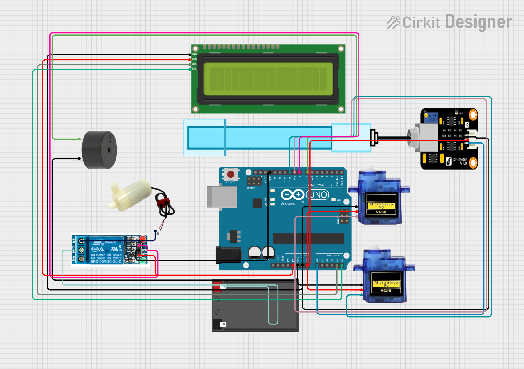
Circuit Documentation
Summary
This circuit is designed to monitor the pH level of a solution and respond to extreme pH values by activating an alarm and controlling a water pump. The system uses an Arduino UNO as the central microcontroller to read pH values from a pH meter, display the readings on an I2C LCD screen, and control two micro servos, a buzzer, and a water pump through a 5V relay. The circuit is powered by a battery, and the components are interconnected through various digital and analog pins on the Arduino UNO.
Component List
Microcontroller
- Arduino UNO: A microcontroller board based on the ATmega328P, with a variety of digital and analog I/O pins.
Sensors
- PH Meter: A sensor used to measure the pH level of a solution.
Actuators
- Micro servo 9G (x2): Small servos used for precise positioning.
- 5v mini water pump: A pump used to move water when activated.
- buzzer: An audible alarm device to alert when certain pH levels are detected.
Power Supply
- battery: Provides power to the circuit.
Display
- I2C LCD 16x2 Screen: A 16-character by 2-line display that communicates over the I2C protocol.
Relay
- 5v relay: An electromechanical switch used to control the water pump.
Wiring Details
Arduino UNO
- 5V: Powers the I2C LCD screen and the 5V relay.
- GND: Common ground for the Micro servos, I2C LCD screen, PH Meter, buzzer, and 5V relay.
- Vin: Connected to the +5V pins of the Micro servos and the VCC of the PH Meter.
- A0: Reads the signal from the PH Meter.
- A4 (SDA): I2C data line for the I2C LCD screen.
- A5 (SCL): I2C clock line for the I2C LCD screen.
- D7: Controls the buzzer.
- D8: Controls the relay input.
- D9: PWM control for one Micro servo.
- D10: PWM control for the other Micro servo.
Micro servo 9G
- GND: Connected to the Arduino's ground.
- +5V: Powered by the Arduino's Vin.
- PWM: Receives PWM signal from Arduino's digital pins D9 and D10.
PH Meter
- Signal: Connected to Arduino's analog pin A0.
- VCC: Powered by the Arduino's Vin.
- GND: Connected to the Arduino's ground.
I2C LCD 16x2 Screen
- SCL: Connected to Arduino's A5.
- SDA: Connected to Arduino's A4.
- VCC (5V): Powered by the Arduino's 5V.
- GND: Connected to the Arduino's ground.
5v relay
- VCC: Powered by the Arduino's 5V.
- GND: Connected to the Arduino's ground.
- In: Controlled by Arduino's digital pin D8.
- Normally Open: Connected to the positive pin of the water pump.
- Common terminal: Connected to the positive terminal of the battery.
5v mini water pump
- positive pin: Connected to the Normally Open terminal of the relay.
- negative pin: Presumed to be connected to the negative terminal of the battery (not explicitly stated in the net list).
buzzer
- PIN: Controlled by Arduino's digital pin D7.
- GND: Connected to the Arduino's ground.
Documented Code
#include <Wire.h>
#include <LiquidCrystal_I2C.h>
#include <Servo.h>

LiquidCrystal_I2C lcd(0x27, 16, 2);  // Initialize the I2C LCD (address may vary)

const int pHSensorPin = A0;
const int buzzerPin = 7;
const int waterPumpPin = 8;
const int servoPin1 = 9;
const int servoPin2 = 10;

Servo servo1;
Servo servo2;

void setup() {
  // Initialize components
  lcd.begin(16, 2);  // Set LCD size to 16x2
  lcd.backlight();

  servo1.attach(servoPin1);
  servo2.attach(servoPin2);
  pinMode(buzzerPin, OUTPUT);
  pinMode(waterPumpPin, OUTPUT);

  // Set initial states
  digitalWrite(buzzerPin, LOW);
  digitalWrite(waterPumpPin, LOW);
  servo1.write(0);  // Set servos to 0 degrees initially
  servo2.write(0);
}

void loop() {
  float pHValue = analogRead(pHSensorPin) * (5.0 / 1023.0) * 3.5;  // Adjust 3.5 factor based on sensor calibration

  lcd.clear();
  lcd.setCursor(0, 0);
  lcd.print("pH Value: ");
  lcd.print(pHValue);

  if (pHValue < 4.0) {
    lcd.setCursor(0, 1);
    lcd.print("Acidic");
    activateAlarm();
  }
  else if (pHValue > 10.0) {
    lcd.setCursor(0, 1);
    lcd.print("Basic");
    activateAlarm();
  }
  else {
    lcd.setCursor(0, 1);
    lcd.print("Neutral");
    deactivateAlarm();
  }

  delay(1000);  // Wait 1 second before next reading
}

void activateAlarm() {
  servo1.write(90);  // Rotate servos to 90 degrees
  servo2.write(90);
  digitalWrite(buzzerPin, HIGH);  // Turn on buzzer
  delay(2000);  // Wait for 2 seconds
  digitalWrite(waterPumpPin, HIGH);  // Start water pump
}

void deactivateAlarm() {
  digitalWrite(buzzerPin, LOW);  // Turn off buzzer
  digitalWrite(waterPumpPin, LOW);  // Turn off water pump
  servo1.write(0);  // Return servos to original position
  servo2.write(0);
}
This code is designed to run on the Arduino UNO microcontroller. It initializes the connected components, reads the pH value from the sensor, displays the value on the LCD, and activates or deactivates the alarm and water pump based on the pH level. The servos are used as part of the alarm mechanism, presumably to perform a physical action when the alarm state is activated.