
Circuit Documentation
Summary
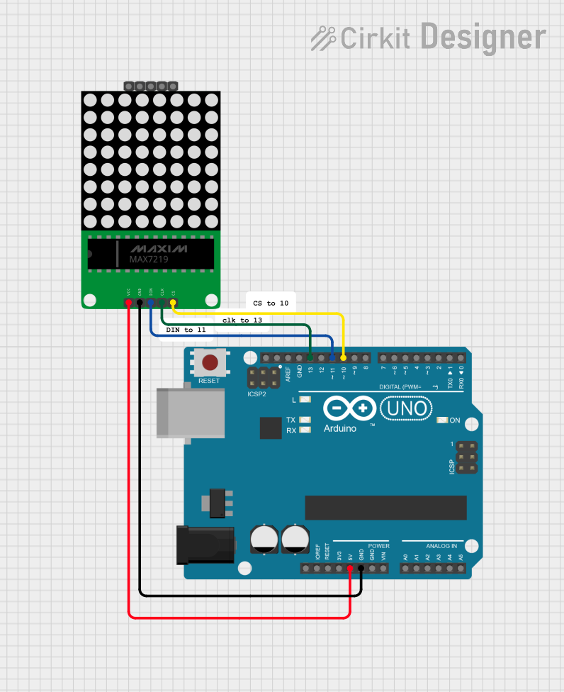
This circuit involves an Arduino UNO microcontroller connected to a MAX7219 8x8 LED Matrix. The Arduino UNO controls the LED matrix by sending signals through specific digital pins. The circuit is powered by the 5V output from the Arduino UNO.
Component List
Arduino UNO
- Description: A microcontroller board based on the ATmega328P.
- Pins: UNUSED, IOREF, Reset, 3.3V, 5V, GND, Vin, A0, A1, A2, A3, A4, A5, SCL, SDA, AREF, D13, D12, D11, D10, D9, D8, D7, D6, D5, D4, D3, D2, D1, D0
MAX7219 8x8 LED Matrix
- Description: A display driver IC that controls an 8x8 LED matrix.
- Pins: CS, CLK, DIN, GND, VCC, CS(OUT), CLK(OUT), DOUT, VCC(OUT)
Comment
- Description: Placeholder for comments in the circuit design.
- Pins: None
Wiring Details
Arduino UNO
- D10: Connected to CS of MAX7219 8x8 LED Matrix
- D13: Connected to CLK of MAX7219 8x8 LED Matrix
- D11: Connected to DIN of MAX7219 8x8 LED Matrix
- GND: Connected to GND of MAX7219 8x8 LED Matrix
- 5V: Connected to VCC of MAX7219 8x8 LED Matrix
MAX7219 8x8 LED Matrix
- CS: Connected to D10 of Arduino UNO
- CLK: Connected to D13 of Arduino UNO
- DIN: Connected to D11 of Arduino UNO
- GND: Connected to GND of Arduino UNO
- VCC: Connected to 5V of Arduino UNO
Documented Code
Arduino UNO Code
void setup() {
  // put your setup code here, to run once:

}

void loop() {
  // put your main code here, to run repeatedly:

}
This code is a basic template for the Arduino UNO. The setup() function is where you initialize your settings, and the loop() function is where the main code runs repeatedly. You can add your specific logic to control the MAX7219 8x8 LED Matrix in these functions.