Cirkit Designer
Your all-in-one circuit design IDE
Home /
Project Documentation
18650 Li-ion Battery Pack with BMS for 5V Power Supply

Circuit Documentation
Summary
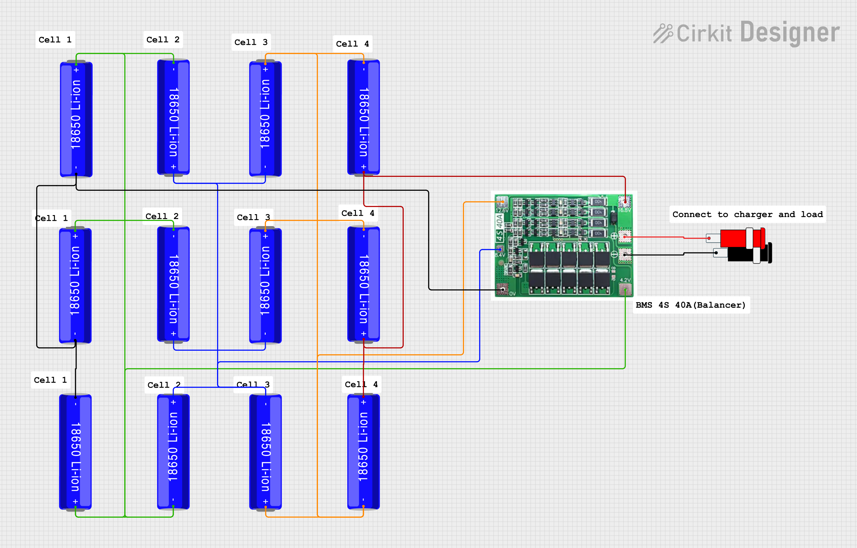
This circuit is designed to manage and utilize a series of 18650 Li-ion batteries connected through a Battery Management System (BMS) to provide a stable 5V output. The BMS ensures the batteries are charged and discharged safely, while the connector provides the necessary output voltage for external devices.
Component List
18650 Li-ion Battery
- Description: Rechargeable lithium-ion battery.
- Pins:
+,- - Purpose: Provides power to the circuit.
BMS 4S 40A
- Description: Battery Management System for 4-series Li-ion batteries.
- Pins:
12.4 V,0V,4.2 V,16.8 V,+V,-V,8.4 V - Purpose: Manages charging and discharging of the batteries.
Connector 5V
- Description: Connector providing 5V output.
- Pins:
GND,VCC - Purpose: Provides a stable 5V output for external devices.
Comment
- Description: Placeholder for comments.
- Pins: None
- Purpose: Used for documentation and notes within the circuit design.
Wiring Details
18650 Li-ion Battery
Battery 1
-connected to0Vof BMS+connected to4.2 Vof BMS
Battery 2
-connected to0Vof BMS+connected to4.2 Vof BMS
Battery 3
-connected to0Vof BMS+connected to4.2 Vof BMS
Battery 4
-connected to4.2 Vof BMS+connected to8.4 Vof BMS
Battery 5
-connected to4.2 Vof BMS+connected to8.4 Vof BMS
Battery 6
-connected to8.4 Vof BMS+connected to12.4 Vof BMS
Battery 7
-connected to8.4 Vof BMS+connected to12.4 Vof BMS
Battery 8
-connected to12.4 Vof BMS+connected to16.8 Vof BMS
Battery 9
-connected to12.4 Vof BMS+connected to16.8 Vof BMS
Battery 10
-connected to16.8 Vof BMS+connected to16.8 Vof BMS
Battery 11
-connected to16.8 Vof BMS+connected to16.8 Vof BMS
Battery 12
-connected to16.8 Vof BMS+connected to16.8 Vof BMS
BMS 4S 40A
0Vconnected to-of Battery 1, Battery 2, and Battery 34.2 Vconnected to+of Battery 1, Battery 2, and Battery 3, and-of Battery 4 and Battery 58.4 Vconnected to+of Battery 4 and Battery 5, and-of Battery 6 and Battery 712.4 Vconnected to+of Battery 6 and Battery 7, and-of Battery 8 and Battery 916.8 Vconnected to+of Battery 8 and Battery 9, and+of Battery 10, Battery 11, and Battery 12-Vconnected toGNDof Connector 5V+Vconnected toVCCof Connector 5V
Connector 5V
GNDconnected to-Vof BMSVCCconnected to+Vof BMS
Code
There is no microcontroller code provided for this circuit.