Simple 9V Battery-Powered Red LED Circuit
Circuit Documentation
Summary of the Circuit
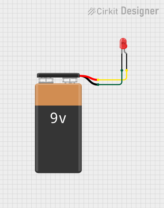
This simple circuit consists of a red two-pin LED and a 9V battery. The LED is connected to the battery in a way that allows current to flow through the LED, causing it to emit light. The circuit does not include any microcontrollers or complex components, making it a straightforward example of a basic electrical circuit.
Component List
LED: Two Pin (red)
- Description: A basic red light-emitting diode (LED) with two pins: an anode and a cathode.
- Purpose: To emit red light when powered by a suitable voltage.
9V Battery
- Description: A standard 9V battery with a positive (+) and a negative (-) terminal.
- Purpose: To provide the necessary power to the LED to allow it to function.
Wiring Details
LED: Two Pin (red)
- Cathode: Connected to the negative (-) terminal of the 9V battery.
- Anode: Connected to the positive (+) terminal of the 9V battery.
9V Battery
- Positive (+) Terminal: Connected to the anode of the LED.
- Negative (-) Terminal: Connected to the cathode of the LED.
Documented Code
There appears to be a misunderstanding in the provided inputs. The code provided is associated with microcontroller instance IDs, but the circuit described does not include any microcontrollers. Therefore, there is no embedded code to document for this circuit.
If there were microcontrollers and associated code in the circuit, this section would include the code with comments explaining its functionality. Since there are no microcontrollers in this circuit, this section is not applicable.
Please note that the provided inputs seem to be inconsistent with the typical use of microcontrollers in circuits. If there are any microcontrollers in the circuit, please provide the correct details, and the documentation will be updated accordingly.