
Arduino UNO Bluetooth-Controlled Robotic Car with L298N Motor Driver
View and Edit Project In Cirkit Designer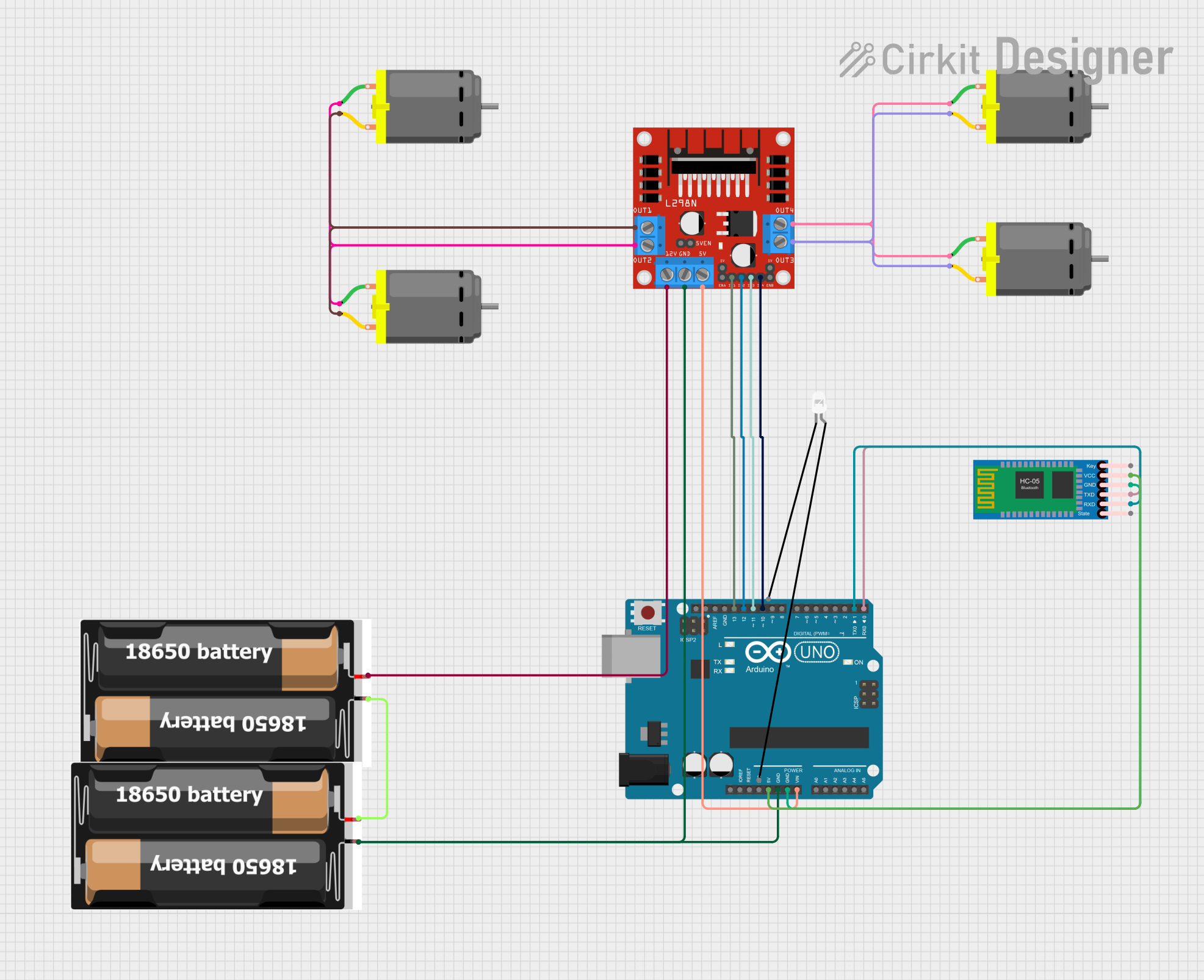
Circuit Documentation
Summary
This circuit is designed to control multiple DC motors using an Arduino UNO and an L298N motor driver. The circuit also includes an HC-05 Bluetooth module for wireless communication and a power supply using 2x 18650 batteries. The Arduino UNO is programmed to receive commands via Bluetooth and control the motors accordingly.
Component List
Arduino UNO
- Description: Microcontroller board based on the ATmega328P.
- Pins: UNUSED, IOREF, Reset, 3.3V, 5V, GND, Vin, A0, A1, A2, A3, A4, A5, SCL, SDA, AREF, D13, D12, D11, D10, D9, D8, D7, D6, D5, D4, D3, D2, D1, D0
DC Motor
- Description: Standard DC motor.
- Pins: pin 1, pin 2
L298N DC Motor Driver
- Description: Dual H-Bridge motor driver.
- Pins: OUT1, OUT2, 12V, GND, 5V, OUT3, OUT4, 5V-ENA-JMP-I, 5V-ENA-JMP-O, +5V-J1, +5V-J2, ENA, IN1, IN2, IN3, IN4, ENB
2x 18650
- Description: Battery pack with two 18650 batteries.
- Pins: vcc, gnd
HC-05 Bluetooth Module
- Description: Bluetooth module for wireless communication.
- Pins: Key, VCC, GND, TXD, RXD, State
LED: Two Pin (white)
- Description: Standard white LED.
- Pins: cathode, anode
Wiring Details
Arduino UNO
- 5V connected to VCC of HC-05 Bluetooth Module
- GND connected to GND of HC-05 Bluetooth Module and GND of L298N DC Motor Driver
- Vin connected to 5V of L298N DC Motor Driver
- D13 connected to IN1 of L298N DC Motor Driver
- D12 connected to IN2 of L298N DC Motor Driver
- D11 connected to IN3 of L298N DC Motor Driver
- D10 connected to IN4 of L298N DC Motor Driver
- D1 connected to RXD of HC-05 Bluetooth Module
- D0 connected to TXD of HC-05 Bluetooth Module
DC Motor
- pin 1 of first motor connected to OUT4 of L298N DC Motor Driver
- pin 2 of first motor connected to OUT3 of L298N DC Motor Driver
- pin 1 of second motor connected to OUT4 of L298N DC Motor Driver
- pin 2 of second motor connected to OUT3 of L298N DC Motor Driver
- pin 1 of third motor connected to OUT2 of L298N DC Motor Driver
- pin 2 of third motor connected to OUT1 of L298N DC Motor Driver
- pin 1 of fourth motor connected to OUT2 of L298N DC Motor Driver
- pin 2 of fourth motor connected to OUT1 of L298N DC Motor Driver
L298N DC Motor Driver
- GND connected to GND of Arduino UNO and GND of 2x 18650 battery pack
- 5V connected to Vin of Arduino UNO
- 12V connected to vcc of 2x 18650 battery pack
- IN1 connected to D13 of Arduino UNO
- IN2 connected to D12 of Arduino UNO
- IN3 connected to D11 of Arduino UNO
- IN4 connected to D10 of Arduino UNO
- OUT1 connected to pin 2 of third and fourth DC motors
- OUT2 connected to pin 1 of third and fourth DC motors
- OUT3 connected to pin 2 of first and second DC motors
- OUT4 connected to pin 1 of first and second DC motors
2x 18650
- vcc connected to 12V of L298N DC Motor Driver
- gnd connected to GND of L298N DC Motor Driver and GND of Arduino UNO
HC-05 Bluetooth Module
- VCC connected to 5V of Arduino UNO
- GND connected to GND of Arduino UNO
- TXD connected to D0 of Arduino UNO
- RXD connected to D1 of Arduino UNO
Code Documentation
#define in1 5 //L298n Motor Driver pins.
#define in2 6
#define in3 10
#define in4 11
#define LED 13

int command; //Int to store app command state.
int Speed = 204; // 0 - 255.
int Speedsec;
int buttonState = 0;
int lastButtonState = 0;
int Turnradius = 0; //Set the radius of a turn, 0 - 255 Note:the robot will malfunction if this is higher than int Speed.
int brakeTime = 45;
int brkonoff = 1; //1 for the electronic braking system, 0 for normal.

void setup() {
  pinMode(in1, OUTPUT);
  pinMode(in2, OUTPUT);
  pinMode(in3, OUTPUT);
  pinMode(in4, OUTPUT);
  pinMode(LED, OUTPUT); //Set the LED pin.
  Serial.begin(9600);  //Set the baud rate to your Bluetooth module.
}

void loop() {
  if (Serial.available() > 0) {
    command = Serial.read();
    Stop(); //Initialize with motors stopped.
    switch (command) {
      case 'F':
        forward();
        break;
      case 'B':
        back();
        break;
      case 'L':
        left();
        break;
      case 'R':
        right();
        break;
      case 'G':
        forwardleft();
        break;
      case 'I':
        forwardright();
        break;
      case 'H':
        backleft();
        break;
      case 'J':
        backright();
        break;
      case '0':
        Speed = 100;
        break;
      case '1':
        Speed = 140;
        break;
      case '2':
        Speed = 153;
        break;
      case '3':
        Speed = 165;
        break;
      case '4':
        Speed = 178;
        break;
      case '5':
        Speed = 191;
        break;
      case '6':
        Speed = 204;
        break;
      case '7':
        Speed = 216;
        break;
      case '8':
        Speed = 229;
        break;
      case '9':
        Speed = 242;
        break;
      case 'q':
        Speed = 255;
        break;
    }
    Speedsec = Turnradius;
    if (brkonoff == 1) {
      brakeOn();
    } else {
      brakeOff();
    }
  }
}

void forward() {
  analogWrite(in1, Speed);
  analogWrite(in3, Speed);
}

void back() {
  analogWrite(in2, Speed);
  analogWrite(in4, Speed);
}

void left() {
  analogWrite(in3, Speed);
  analogWrite(in2, Speed);
}

void right() {
  analogWrite(in4, Speed);
  analogWrite(in1, Speed);
}

void forwardleft() {
  analogWrite(in1, Speedsec);
  analogWrite(in3, Speed);
}

void forwardright() {
  analogWrite(in1, Speed);
  analogWrite(in3, Speedsec);
}

void backright() {
  analogWrite(in2, Speed);
  analogWrite(in4, Speedsec);
}

void backleft() {
  analogWrite(in2, Speedsec);
  analogWrite(in4, Speed);
}

void Stop() {
  analogWrite(in1, 0);
  analogWrite(in2, 0);
  analogWrite(in3, 0);
  analogWrite(in4, 0);
}

void brakeOn() {
  //Here's the future use: an electronic braking system!
  // read the pushbutton input pin:
  buttonState = command;
  // compare the buttonState to its previous state
  if (buttonState != lastButtonState) {
    // if the state has changed, increment the counter
    if (buttonState == 'S') {
      if (lastButtonState != buttonState) {
        digitalWrite(in1, HIGH);
        digitalWrite(in2, HIGH);
        digitalWrite(in3, HIGH);
        digitalWrite(in4, HIGH);
        delay(brakeTime);
        Stop();
      }
    }