
Arduino UNO Controlled Stepper Motor Elevator with Pushbutton Floor Selection
View and Edit Project In Cirkit Designer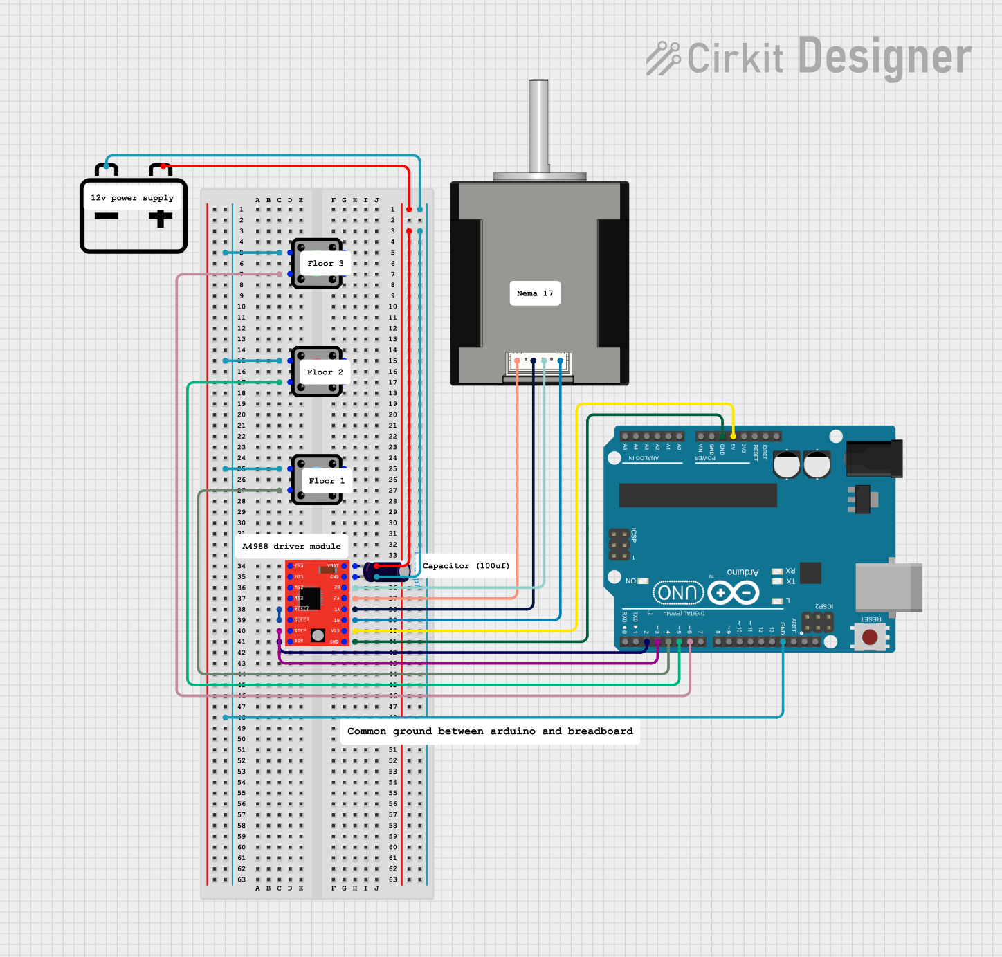
Circuit Documentation
Summary
This circuit is designed to control a Nema 17 stepper motor using an Arduino UNO and an A4988 stepper motor driver. The circuit also includes three pushbuttons to select different floor positions for the stepper motor. The motor's position is controlled by the Arduino, which reads the state of the pushbuttons and sends appropriate signals to the A4988 driver to move the motor to the desired position.
Component List
Arduino UNO
- Description: Microcontroller board based on the ATmega328P.
- Pins: UNUSED, IOREF, Reset, 3.3V, 5V, GND, Vin, A0, A1, A2, A3, A4, A5, SCL, SDA, AREF, D13, D12, D11, D10, D9, D8, D7, D6, D5, D4, D3, D2, D1, D0
Nema 17 42-STH48
- Description: Bipolar stepper motor.
- Pins: A2 (black), A1 Green, B2 Red, B1 Blue
A4988 Stepper Motor Driver (Red)
- Description: Stepper motor driver carrier.
- Pins: ENABLE, MS1, MS2, MS3, RESET, SLEEP, STEP, DIR, VMOT, GND, 2B, 2A, 1A, 1B, VDD
Pushbutton (x3)
- Description: Momentary pushbutton switch.
- Pins: Pin 2, Pin 1, Pin 3, Pin 4
12v Battery
- Description: Power source.
- Pins: -, +
Electrolytic Capacitor
- Description: Capacitor with a capacitance of 1µF.
- Pins: -, +
- Properties: Capacitance: 1µF
Wiring Details
Arduino UNO
- GND: Connected to Pin 2 of all three pushbuttons.
- D6: Connected to Pin 3 of the first pushbutton.
- D5: Connected to Pin 3 of the second pushbutton.
- D4: Connected to Pin 3 of the third pushbutton.
- D3: Connected to STEP pin of the A4988 Stepper Motor Driver.
- 5V: Connected to VDD pin of the A4988 Stepper Motor Driver.
- D2: Connected to DIR pin of the A4988 Stepper Motor Driver.
- GND: Connected to GND pin of the A4988 Stepper Motor Driver.
Nema 17 42-STH48
- A2 (black): Connected to 2A pin of the A4988 Stepper Motor Driver.
- A1 Green: Connected to 1A pin of the A4988 Stepper Motor Driver.
- B2 Red: Connected to 2B pin of the A4988 Stepper Motor Driver.
- B1 Blue: Connected to 1B pin of the A4988 Stepper Motor Driver.
A4988 Stepper Motor Driver (Red)
- VMOT: Connected to the negative pin of the Electrolytic Capacitor and the positive terminal of the 12v Battery.
- GND: Connected to the positive pin of the Electrolytic Capacitor and the negative terminal of the 12v Battery.
- 2B: Connected to B2 Red pin of the Nema 17 Stepper Motor.
- 2A: Connected to A2 (black) pin of the Nema 17 Stepper Motor.
- RESET: Connected to SLEEP pin of the A4988 Stepper Motor Driver.
- 1A: Connected to A1 Green pin of the Nema 17 Stepper Motor.
- 1B: Connected to B1 Blue pin of the Nema 17 Stepper Motor.
- STEP: Connected to D3 pin of the Arduino UNO.
- VDD: Connected to 5V pin of the Arduino UNO.
- DIR: Connected to D2 pin of the Arduino UNO.
- GND: Connected to GND pin of the Arduino UNO.
Pushbutton 1
- Pin 2: Connected to GND pin of the Arduino UNO.
- Pin 3: Connected to D6 pin of the Arduino UNO.
Pushbutton 2
- Pin 2: Connected to GND pin of the Arduino UNO.
- Pin 3: Connected to D5 pin of the Arduino UNO.
Pushbutton 3
- Pin 2: Connected to GND pin of the Arduino UNO.
- Pin 3: Connected to D4 pin of the Arduino UNO.
12v Battery
- +: Connected to VMOT pin of the A4988 Stepper Motor Driver and the negative pin of the Electrolytic Capacitor.
- -: Connected to GND pin of the A4988 Stepper Motor Driver and the positive pin of the Electrolytic Capacitor.
Electrolytic Capacitor
- -: Connected to VMOT pin of the A4988 Stepper Motor Driver and the positive terminal of the 12v Battery.
- +: Connected to GND pin of the A4988 Stepper Motor Driver and the negative terminal of the 12v Battery.
Code Documentation
#include <AccelStepper.h>

// Define pin connections
const int dirPin = 2;
const int stepPin = 3;
const int buttonFloor1 = 4; // Button for floor 1
const int buttonFloor2 = 5; // Button for floor 2
const int buttonFloor3 = 6; // Button for floor 3

// Define motor interface type
#define motorInterfaceType 1

// Creates an instance of AccelStepper
AccelStepper myStepper(motorInterfaceType, stepPin, dirPin);

// Define step positions for each floor (adjust these values for your setup)
const long stepsPerFloor[] = {0, 1500, 2800}; // Example: Floor 1 = 0, Floor 2 = 2000, Floor 3 = 2800
long currentFloor = 1;  // Start at floor 1
bool isMoving = false;  // Flag to check if the motor is moving

void setup() {
    // Set motor parameters for optimized speed and acceleration
    myStepper.setMaxSpeed(500);
    myStepper.setAcceleration(200);

    // Initialize pins
    pinMode(buttonFloor1, INPUT_PULLUP);
    pinMode(buttonFloor2, INPUT_PULLUP);
    pinMode(buttonFloor3, INPUT_PULLUP);
}

void loop() {
    // Read button states
    bool floor1Pressed = digitalRead(buttonFloor1) == LOW;
    bool floor2Pressed = digitalRead(buttonFloor2) == LOW;
    bool floor3Pressed = digitalRead(buttonFloor3) == LOW;

    // Handle button presses for each floor
    if (floor1Pressed && currentFloor != 1 && !isMoving) {
        moveToFloor(1);
    } else if (floor2Pressed && currentFloor != 2 && !isMoving) {
        moveToFloor(2);
    } else if (floor3Pressed && currentFloor != 3 && !isMoving) {
        moveToFloor(3);
    }

    // Run the motor to reach the target position
    if (myStepper.distanceToGo() != 0) {
        myStepper.run();
    } else if (isMoving) {
        isMoving = false;  // Reset the moving flag
    }
}

// Function to move to a specific floor
void moveToFloor(int targetFloor) {
    currentFloor = targetFloor;
    myStepper.moveTo(stepsPerFloor[currentFloor - 1]); // Use the specific step count for the target floor
    isMoving = true;  // Set the moving flag
    delay(300);       // Debounce delay
}
This code is designed to control the stepper motor to move to different floor positions based on the pushbutton inputs. The AccelStepper library is used to manage the motor's movements, and the motor's speed and acceleration are set for optimal performance. The moveToFloor function is called when a button is pressed to move the motor to the corresponding floor position.