
Arduino UNO Controlled RGB LED Light Show with Sound Detection
View and Edit Project In Cirkit Designer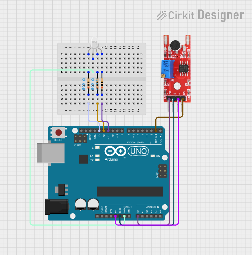
Circuit Documentation
Summary
This circuit is designed to interface an Arduino UNO with an RGB LED and a KY-038 sound sensor module. The Arduino UNO controls the RGB LED by toggling its red, green, and blue channels to create a blinking effect. The KY-038 module is connected to the Arduino for sound detection, with its analog and digital outputs interfaced with the Arduino's analog and digital pins, respectively.
Component List
Arduino UNO
- Microcontroller board based on the ATmega328P
- It has 14 digital input/output pins, 6 analog inputs, a 16 MHz quartz crystal, a USB connection, a power jack, an ICSP header, and a reset button.
KY-038 Sound Sensor Module
- A sound detection sensor that includes a microphone and a built-in amplifier for audio signal processing.
- It provides both analog and digital outputs.
RGB LED (Wokwi compatible)
- A light-emitting diode that can emit red, green, and blue light.
- It has four pins: one for each color and a common cathode (COM).
Resistor (200 Ohms)
- A passive two-terminal electrical component that implements electrical resistance as a circuit element.
- Used to limit current and divide voltages in the circuit.
Wiring Details
Arduino UNO
- Digital Pin 13 (D13) is connected to a 200 Ohm resistor, which is then connected to the red channel of the RGB LED.
- Digital Pin 12 (D12) is connected to a 200 Ohm resistor, which is then connected to the green channel of the RGB LED.
- Digital Pin 11 (D11) is connected to a 200 Ohm resistor, which is then connected to the blue channel of the RGB LED.
- Ground (GND) is connected to the common cathode (COM) of the RGB LED.
- 5V pin provides power to the KY-038 sound sensor module.
- Ground (GND) is also connected to the ground (G) of the KY-038 sound sensor module.
- Analog Pin 0 (A0) is connected to the analog output (A0) of the KY-038 sound sensor module.
- Digital Pin 1 (D1) is connected to the digital output (D0) of the KY-038 sound sensor module.
KY-038 Sound Sensor Module
- "+" pin is connected to the 5V output from the Arduino UNO.
- "G" pin is connected to the ground (GND) on the Arduino UNO.
- "A0" pin is connected to the Analog Pin 0 (A0) on the Arduino UNO.
- "D0" pin is connected to the Digital Pin 1 (D1) on the Arduino UNO.
RGB LED (Wokwi compatible)
- "R" pin is connected through a 200 Ohm resistor to Digital Pin 13 (D13) on the Arduino UNO.
- "G" pin is connected through a 200 Ohm resistor to Digital Pin 12 (D12) on the Arduino UNO.
- "B" pin is connected through a 200 Ohm resistor to Digital Pin 11 (D11) on the Arduino UNO.
- "COM" pin is connected to the Ground (GND) on the Arduino UNO.
Resistor (200 Ohms)
- One pin is connected to the Arduino UNO's digital output pins (D13, D12, D11) and the other pin to the respective RGB LED pins (R, G, B).
Documented Code
void setup() {
  // Initialize RGB LED pins as outputs
  pinMode(13, OUTPUT); // LED to Red
  pinMode(12, OUTPUT); // LED to Green
  pinMode(11, OUTPUT); // LED to Blue
}

void loop() {
  // Red LED on for 2 seconds, then off
  digitalWrite(13, HIGH);
  delay(2000);
  digitalWrite(13, LOW);
  delay(2000);

  // Green LED on for 2 seconds, then off
  digitalWrite(12, HIGH);
  delay(2000);
  digitalWrite(12, LOW);
  delay(2000);

  // Blue LED on for 2 seconds, then off
  digitalWrite(11, HIGH);
  delay(2000);
  digitalWrite(11, LOW);
  delay(2000);
}
This code is designed to sequentially blink the red, green, and blue channels of the RGB LED connected to the Arduino UNO. Each color is turned on for two seconds and then turned off before the next color is activated. The cycle repeats indefinitely.