Cirkit Designer
Your all-in-one circuit design IDE
Home /
Project Documentation
Arduino Nano RFID Access Control with Servo and Buzzer Notification
Circuit Documentation
Summary
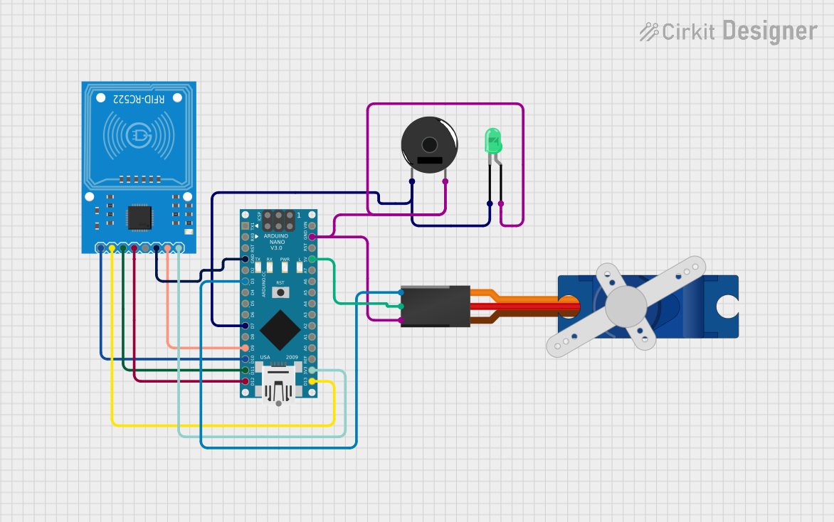
The circuit in question is designed to interface an Arduino Nano with an RFID-RC522 module, a Tower Pro SG90 servo motor, a piezo buzzer, and a green LED. The purpose of the circuit is to detect RFID tags, actuate a servo, and provide audio-visual feedback upon successful tag detection. The Arduino Nano serves as the central processing unit, controlling the RFID reader for tag detection, driving the servo motor to a specific position, and triggering the buzzer and LED to indicate the detection event.
Component List
Arduino Nano
- Microcontroller board based on the ATmega328P
- It has a variety of digital and analog I/O pins
- Capable of serial communication, SPI, and I2C
RFID-RC522
- RFID reader/writer module
- Operates at 13.56 MHz for communication with RFID tags
- Interfaces with the Arduino via SPI
Tower Pro SG90 Servo
- Small and lightweight servo motor
- Capable of precise angular positioning
- Controlled by PWM signal
Piezo Buzzer
- Simple electronic device that produces sound
- Used to provide audio feedback
LED: Two Pin (green)
- Basic green LED
- Used for visual indication
Wiring Details
Arduino Nano
D7connected to the cathode of the green LED and pin 1 of the piezo buzzerGNDconnected to the anode of the green LED, GND of the servo, and pin 2 of the piezo buzzerD3connected to the signal pin of the servo5Vconnected to the +5V of the servo3V3connected to the 3.3V of the RFID-RC522D9connected to the RST pin of the RFID-RC522D10connected to the SDA pin of the RFID-RC522D11/MOSIconnected to the MOSI pin of the RFID-RC522D12/MISOconnected to the MISO pin of the RFID-RC522D13/SCKconnected to the SCK pin of the RFID-RC522
RFID-RC522
3.3Vconnected to 3V3 of the Arduino NanoGNDconnected to GND of the Arduino NanoRSTconnected to D9 of the Arduino NanoSDAconnected to D10 of the Arduino NanoMOSIconnected to D11/MOSI of the Arduino NanoMISOconnected to D12/MISO of the Arduino NanoSCKconnected to D13/SCK of the Arduino Nano
Tower Pro SG90 Servo
Signalconnected to D3 of the Arduino Nano+5Vconnected to 5V of the Arduino NanoGNDconnected to GND of the Arduino Nano
Piezo Buzzer
pin 1connected to D7 of the Arduino Nanopin 2connected to GND of the Arduino Nano
LED: Two Pin (green)
cathodeconnected to D7 of the Arduino Nanoanodeconnected to GND of the Arduino Nano
Documented Code
#include <SPI.h>
#include <MFRC522.h>
#include <Servo.h>

#define SS_PIN 10
#define RST_PIN 9
MFRC522 rfid(SS_PIN, RST_PIN);

Servo myServo;
int buzzerPin = 7;

void setup() {
  Serial.begin(9600);
  SPI.begin();
  rfid.PCD_Init();

  myServo.attach(3);
  pinMode(buzzerPin, OUTPUT);

  Serial.println("Ready to Scan!");
}

void loop() {
  if (!rfid.PICC_IsNewCardPresent() || !rfid.PICC_ReadCardSerial()) {
    return;
  }

  Serial.println("Card detected!");

  String cardUID = "";
  for (byte i = 0; i < rfid.uid.size; i++) {
    cardUID += String(rfid.uid.uidByte[i], HEX);
  }

  Serial.print("DATA,TIME,");
  Serial.print(cardUID);
  Serial.println(",Accepted");

  digitalWrite(buzzerPin, HIGH);
  delay(100);
  digitalWrite(buzzerPin, LOW);

  myServo.write(90);
  delay(2000);
  myServo.write(0);

  rfid.PICC_HaltA();
}
Code Explanation
- The code begins by including the necessary libraries for SPI communication, RFID interaction, and servo control.
- Two constants
SS_PINandRST_PINare defined for the RFID reader's slave select and reset pins. - An
MFRC522object and aServoobject are instantiated. - The
buzzerPinis defined and set to digital pin 7 on the Arduino Nano. - In the
setup()function, serial communication is initiated, SPI is begun, and the RFID reader is initialized. The servo is attached to pin 3, and the buzzer pin is set as an output. A ready message is printed to the serial monitor. - The
loop()function continuously checks for new RFID cards. If a card is detected, its UID is read and printed to the serial monitor along with a timestamp and an "Accepted" message. - The buzzer is briefly turned on to provide audio feedback, and the servo is actuated to move to 90 degrees, then back to 0 degrees after a delay.
- Finally, the RFID card reading is halted to prepare for the next card detection.