
Arduino UNO-Based Smart Light System with IR Sensors and LDR
View and Edit Project In Cirkit Designer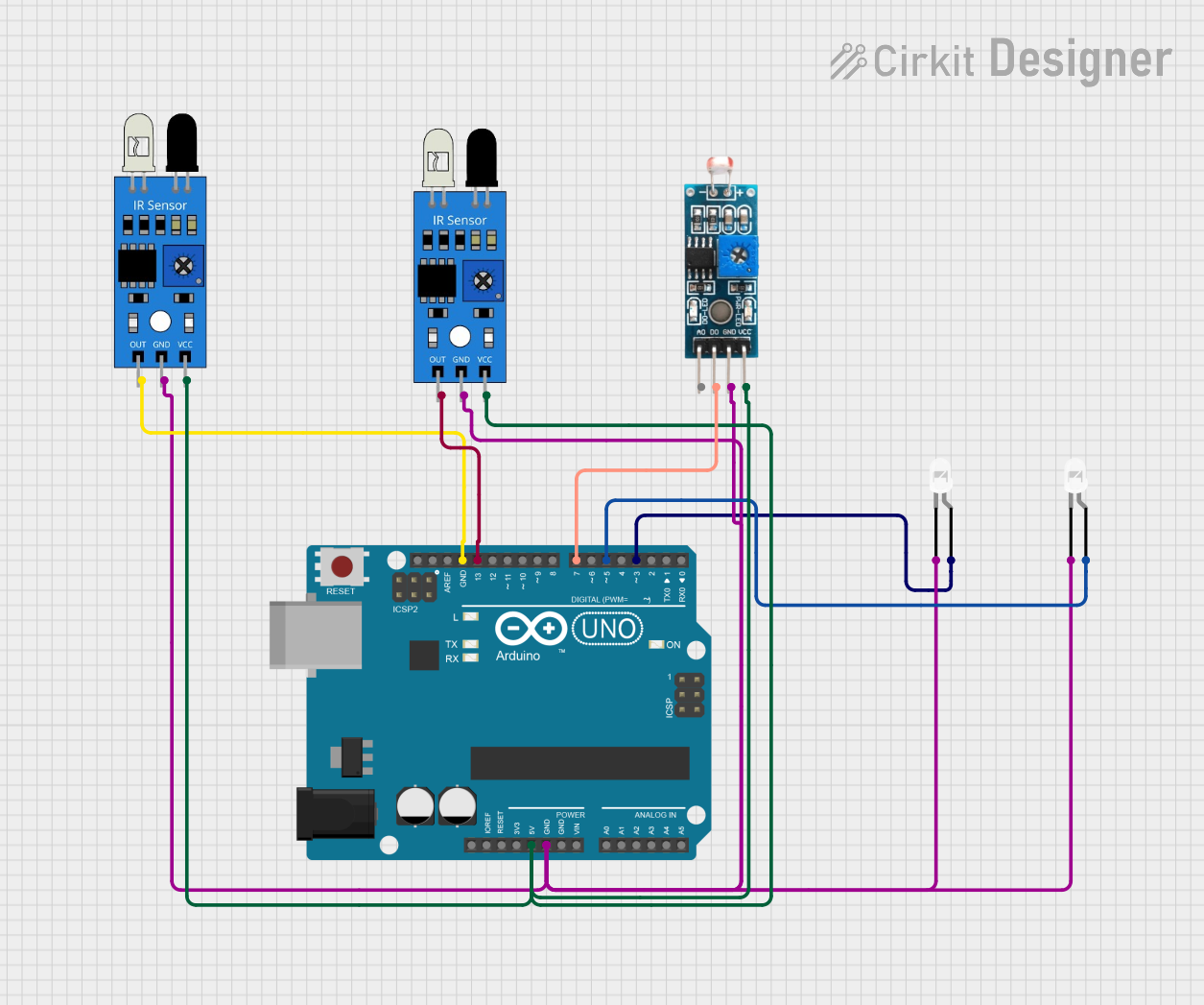
Circuit Documentation
Summary
This circuit involves an Arduino UNO microcontroller interfacing with two IR sensors, an LDR module, and two white LEDs. The circuit is designed to read inputs from the IR sensors and the LDR module and control the LEDs based on the sensor readings.
Component List
Arduino UNO
- Description: A microcontroller board based on the ATmega328P.
- Pins: UNUSED, IOREF, Reset, 3.3V, 5V, GND, Vin, A0, A1, A2, A3, A4, A5, SCL, SDA, AREF, D13, D12, D11, D10, D9, D8, D7, D6, D5, D4, D3, D2, D1, D0
IR Sensor (1)
- Description: An infrared sensor used for detecting objects.
- Pins: out, gnd, vcc
IR Sensor (2)
- Description: An infrared sensor used for detecting objects.
- Pins: out, gnd, vcc
LED: Two Pin (white) (1)
- Description: A white LED with two pins.
- Pins: cathode, anode
LED: Two Pin (white) (2)
- Description: A white LED with two pins.
- Pins: cathode, anode
Module LDR
- Description: A light-dependent resistor module.
- Pins: VCC, GND, DO, AO
Wiring Details
Arduino UNO
- 5V: Connected to VCC of Module LDR, VCC of IR Sensor (1), VCC of IR Sensor (2)
- GND: Connected to GND of Module LDR, GND of IR Sensor (1), GND of IR Sensor (2), cathode of LED (1), cathode of LED (2)
- D13: Connected to out of IR Sensor (2)
- D7: Connected to DO of Module LDR
- D5: Connected to anode of LED (1)
- D3: Connected to anode of LED (2)
IR Sensor (1)
- out: Connected to GND of Arduino UNO
- gnd: Connected to GND of Arduino UNO
- vcc: Connected to 5V of Arduino UNO
IR Sensor (2)
- out: Connected to D13 of Arduino UNO
- gnd: Connected to GND of Arduino UNO
- vcc: Connected to 5V of Arduino UNO
LED: Two Pin (white) (1)
- cathode: Connected to GND of Arduino UNO
- anode: Connected to D5 of Arduino UNO
LED: Two Pin (white) (2)
- cathode: Connected to GND of Arduino UNO
- anode: Connected to D3 of Arduino UNO
Module LDR
- VCC: Connected to 5V of Arduino UNO
- GND: Connected to GND of Arduino UNO
- DO: Connected to D7 of Arduino UNO
- AO: Not connected
Documented Code
int led = 3;
int led1 = 10;
int led2 = 5;
int led3 = 6;
int led4 = 9;

int ldr = A0;

int x1, x2, x3, x4, x5;

void setup()
{
  Serial.begin(9600);
  pinMode(led, OUTPUT);
  pinMode(led1, OUTPUT);
  pinMode(led2, OUTPUT);
  pinMode(led3, OUTPUT);
  pinMode(led4, OUTPUT);

  pinMode(ldr, INPUT);
}

void loop()
{
  int ldrStatus = analogRead(ldr);
  if (ldrStatus <= 300)
  {
    if (analogRead(A1) < 500) // IR 1 CODE
    {
      x1 = 0;
      x2 = 1;
      digitalWrite(led, HIGH);
      digitalWrite(led1, HIGH);
      delay(100); // microsecond
    }
    else
    {
      if (x1 == 0)
      {
        digitalWrite(led, HIGH);
        analogWrite(led, 255 / 5);
        delay(50);
      }
    }

    if (analogRead(A2) < 500) // IR 2 CODE
    {
      x2 = 0;
      x3 = 1;
      digitalWrite(led1, HIGH);
      digitalWrite(led2, HIGH);
      delay(100); // microsecond
    }
    else
    {
      if (x2 == 0)
      {
        digitalWrite(led1, HIGH);
        analogWrite(led1, 255 / 5);
        delay(50);
      }
    }

    if (analogRead(A3) < 500) // IR 3 CODE
    {
      x3 = 0;
      x4 = 1;
      digitalWrite(led2, HIGH);
      digitalWrite(led3, HIGH);
      delay(100); // microsecond
    }
    else
    {
      if (x3 == 0)
      {
        digitalWrite(led2, HIGH);
        analogWrite(led2, 255 / 5);
        delay(50);
      }
    }

    if (analogRead(A4) < 500) // IR 4 CODE
    {
      x4 = 0;
      digitalWrite(led3, HIGH);
      delay(100); // microsecond
    }
    else
    {
      if (x4 == 0)
      {
        digitalWrite(led3, HIGH);
        analogWrite(led3, 255 / 5);
        delay(50);
      }
    }

    if (analogRead(A5) < 500) // IR 5 CODE
    {
      x1 = 1;
      digitalWrite(led4, HIGH);
      digitalWrite(led, HIGH);
      delay(100); // microsecond
    }
    else
    {
      digitalWrite(led4, HIGH);
      analogWrite(led4, 255 / 5);
      delay(50);
    }
  }
  else
  {
    digitalWrite(led, LOW);
    digitalWrite(led1, LOW);
    digitalWrite(led2, LOW);
    digitalWrite(led3, LOW);
    digitalWrite(led4, LOW);
  }
}
This code initializes the pins for the LEDs and the LDR sensor. It reads the LDR status and based on the readings from the IR sensors, it controls the LEDs accordingly.