
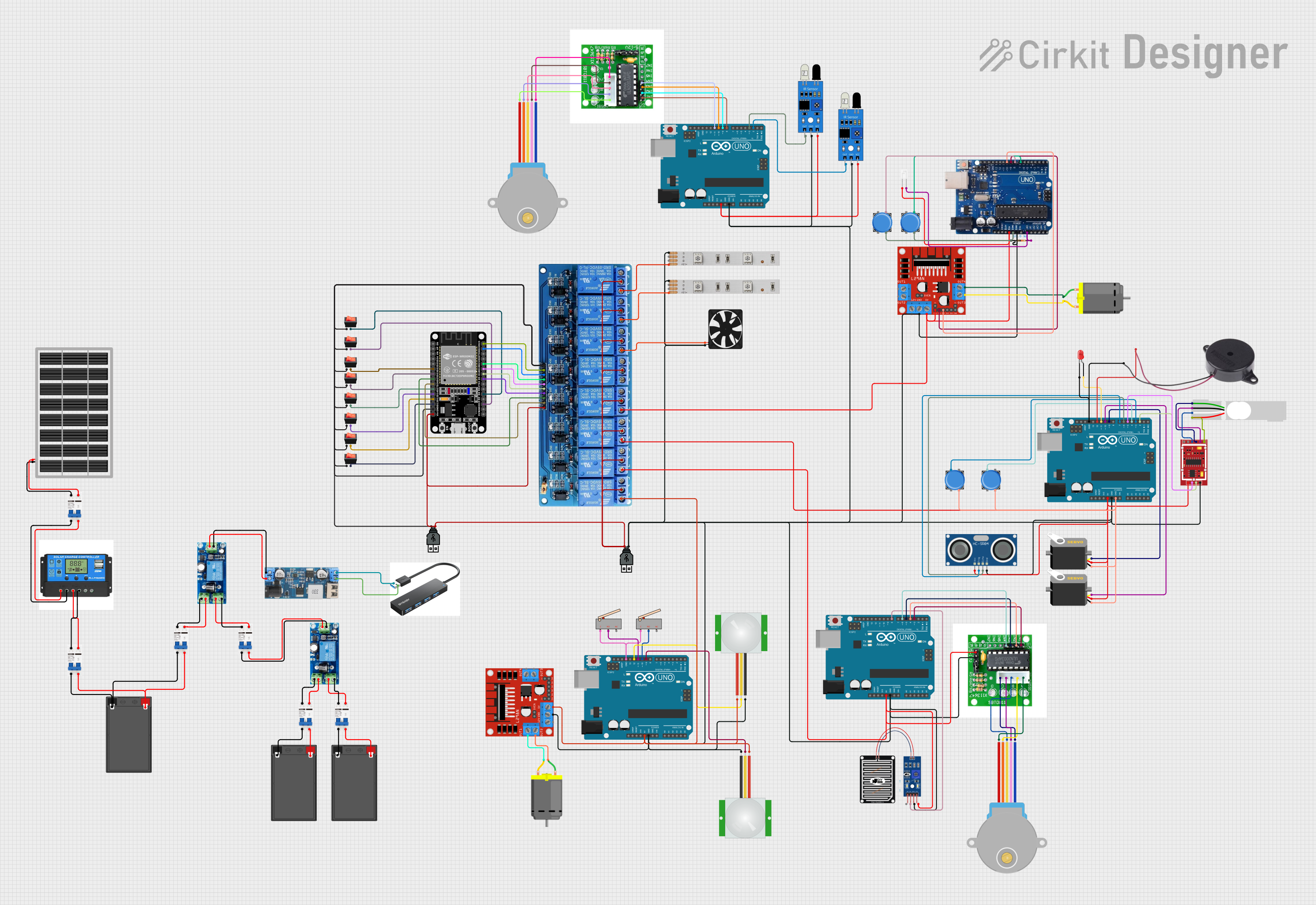
Circuit Documentation
Summary
The circuit in question appears to be a complex system involving multiple microcontrollers, sensors, actuators, power management modules, and user interface elements. The system is likely designed for automation and control purposes, with the ability to sense environmental conditions, manage power, and drive motors and other output devices.
Component List
Microcontrollers
- Arduino UNO: A microcontroller board based on the ATmega328P, with a variety of digital and analog I/O pins.
- ESP32 (30 pin): A microcontroller with Wi-Fi and Bluetooth capabilities, suitable for IoT applications.
Sensors
- IR Sensor: Used for detecting obstacles or for communication via infrared signals.
- PIR Sensor: Passive infrared sensor used for motion detection.
- HC-SR04 Ultrasonic Sensor: Ultrasonic distance sensor.
- RAIN SENSOR: Detects rain or water presence.
- Phototransistor: Sensitive to light, used for detecting light levels.
- HX711 Weighing Sensor Module: Precision 24-bit analog-to-digital converter for weight scales.
Actuators
- DC Motor: Converts electrical energy into mechanical rotation.
- Servo: A rotary actuator that allows for precise control of angular position.
- 28BYJ-48 Stepper Motor: A small stepper motor for precise rotational movement control.
- Fan: Used for cooling or ventilation purposes.
- Buzzer: An audio signaling device.
- LED Strip: A strip of LEDs used for lighting.
Power Management
- 12v 7ah Battery: Provides a 12V power source with a capacity of 7 ampere-hours.
- UPS Module: Uninterruptible power supply module for power backup.
- 12v to 5v Step Down Power Converter: Converts 12V to a stable 5V output.
- Charge Controller: Manages the charging of batteries from solar panels.
- DC MCB: Direct current miniature circuit breaker for overcurrent protection.
- Solar Panel: Converts sunlight into electrical energy.
- 5V 8Channel Relay: An 8-channel relay module for controlling high power devices.
User Interface
- Rocker Switch: A switch for toggling circuit connections.
- Pushbutton: A momentary button switch for user input.
- USB HUB: A hub for connecting multiple USB devices.
Miscellaneous
- Resistor: A passive two-terminal electrical component that implements electrical resistance.
- Load Cell - Red/white/black/green: A transducer that converts force into an electrical signal.
Wiring Details
Microcontrollers
- Arduino UNO: Connected to various sensors, actuators, and other components through its digital and analog I/O pins.
- ESP32 (30 pin): Interfaced with rocker switches, relays, and other components for IoT control capabilities.
Sensors
- IR Sensor: Powered by 5V from the Arduino UNO and outputs signals to the Arduino's digital pins.
- PIR Sensor: Receives power from the Arduino UNO and sends motion detection signals to it.
- HC-SR04 Ultrasonic Sensor: Trigger and echo pins connected to the Arduino UNO for distance measurements.
- RAIN SENSOR: Powered by 5V and sends digital output to the Arduino UNO.
- Phototransistor: Connected to the Arduino Uno R3 for light detection.
- HX711 Weighing Sensor Module: Interfaced with a load cell and connected to the Arduino UNO for weight measurements.
Actuators
- DC Motor: Driven by the L298N DC motor driver, which is controlled by the Arduino Uno R3.
- Servo: Controlled by the Arduino UNO through PWM signals.
- 28BYJ-48 Stepper Motor: Driven by the ULN2003 Driver, which is controlled by the Arduino UNO.
- Fan: Powered by 5V and controlled via a relay.
- Buzzer: Connected to the Arduino UNO for audio alerts.
- LED Strip: Powered by a relay module and controlled by the ESP32.
Power Management
- 12v 7ah Battery: Connected to the UPS module and the charge controller.
- UPS Module: Connected to the batteries, DC MCBs, and the step-down converter.
- 12v to 5v Step Down Power Converter: Steps down voltage for USB HUB and other 5V components.
- Charge Controller: Interfaced with the solar panel and batteries.
- DC MCB: Provides overcurrent protection for the solar panel, batteries, and UPS modules.
- Solar Panel: Connected to the charge controller via a DC MCB.
- 5V 8Channel Relay: Receives control signals from the ESP32 and switches various high-power components.
User Interface
- Rocker Switch: Used to control the power flow to various components.
- Pushbutton: Sends user input to the Arduino Uno R3.
- USB HUB: Receives 5V power from the step-down converter.
Miscellaneous
- Resistor: Connected to the phototransistor and the Arduino Uno R3.
- Load Cell: Interfaced with the HX711 Weighing Sensor Module.
Documented Code
Arduino UNO Code (Instance 1)
#include <Servo.h>

Servo tap_servo;

int sensor_pin = 4;
int tap_servo_pin = 5;
int val;

void setup(){
  pinMode(sensor_pin, INPUT);
  tap_servo.attach(tap_servo_pin);
}

void loop(){
  val = digitalRead(sensor_pin);

  if (val == 0){
    tap_servo.write(0);
  }
  if (val == 1){
    tap_servo.write(180);
  }
}
This code snippet is for controlling a servo motor based on the input from a sensor. The servo is set to rotate to 0 degrees when the sensor input is low and to 180 degrees when the sensor input is high.
Arduino UNO Code (Instance 2)
void setup() {
  // put your setup code here, to run once:

}

void loop() {
  // put your main code here, to run repeatedly:

}
This code snippet is a template with empty setup and loop functions, ready for further development.
ESP32 Code
No code provided for the ESP32 instance.
(Note: The provided code snippets are associated with specific microcontroller instance IDs, but for the purpose of this documentation, the instance IDs have been omitted as per the instructions.)