
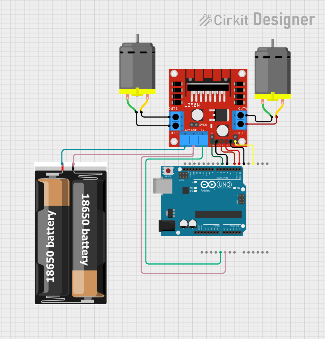
Circuit Documentation
Summary
This circuit is designed to control two DC motors using an Arduino UNO and an H-Bridge motor driver. The motors are powered by a 2x 18650 battery pack. The Arduino UNO is programmed to control the speed and direction of the motors based on an IR remote input.
Component List
Arduino UNO
- Description: A microcontroller board based on the ATmega328P.
- Pins: UNUSED, IOREF, Reset, 3.3V, 5V, GND, Vin, A0, A1, A2, A3, A4, A5, SCL, SDA, AREF, D13, D12, D11, D10, D9, D8, D7, D6, D5, D4, D3, D2, D1, D0
DC Motor (Motor A)
- Description: A simple DC motor.
- Pins: pin 1, pin 2
DC Motor (Motor B)
- Description: A simple DC motor.
- Pins: pin 1, pin 2
H-Bridge Motor Driver (Puente H carrito)
- Description: A motor driver used to control the direction and speed of the motors.
- Pins: OUT1, OUT2, OUT3, OUT4, 12V, GND, 5V, ENA, IN1, IN2, IN3, IN4, ENB, 5VEN
2x 18650 Battery Pack
- Description: A battery pack consisting of two 18650 batteries.
- Pins: vcc, gnd
Wiring Details
Arduino UNO
- 5V connected to 5V of H-Bridge Motor Driver
- GND connected to GND of H-Bridge Motor Driver and gnd of 2x 18650 Battery Pack
- D9 connected to ENA of H-Bridge Motor Driver
- D8 connected to IN1 of H-Bridge Motor Driver
- D7 connected to IN2 of H-Bridge Motor Driver
- D6 connected to IN3 of H-Bridge Motor Driver
- D5 connected to IN4 of H-Bridge Motor Driver
- D3 connected to ENB of H-Bridge Motor Driver
DC Motor (Motor A)
- pin 1 connected to OUT2 of H-Bridge Motor Driver
- pin 2 connected to OUT1 of H-Bridge Motor Driver
DC Motor (Motor B)
- pin 1 connected to OUT4 of H-Bridge Motor Driver
- pin 2 connected to OUT3 of H-Bridge Motor Driver
H-Bridge Motor Driver (Puente H carrito)
- OUT1 connected to pin 2 of DC Motor (Motor A)
- OUT2 connected to pin 1 of DC Motor (Motor A)
- OUT3 connected to pin 2 of DC Motor (Motor B)
- OUT4 connected to pin 1 of DC Motor (Motor B)
- 12V connected to vcc of 2x 18650 Battery Pack
- GND connected to GND of Arduino UNO and gnd of 2x 18650 Battery Pack
- 5V connected to 5V of Arduino UNO
- ENA connected to D9 of Arduino UNO
- IN1 connected to D8 of Arduino UNO
- IN2 connected to D7 of Arduino UNO
- IN3 connected to D6 of Arduino UNO
- IN4 connected to D5 of Arduino UNO
- ENB connected to D3 of Arduino UNO
2x 18650 Battery Pack
- vcc connected to 12V of H-Bridge Motor Driver
- gnd connected to GND of Arduino UNO and GND of H-Bridge Motor Driver
Code Documentation
#include <IRremote.hpp>

const int IR_RECEIVE_PIN = 2;

// Motor A connections
int enA = 9;
int in1 = 8;
int in2 = 7;
// Motor B connections
int enB = 3;
int in3 = 6;
int in4 = 5;

void setup() {
  IrReceiver.begin(IR_RECEIVE_PIN, ENABLE_LED_FEEDBACK); // Start the IR receiver
  // Set all the motor control pins to outputs
  pinMode(enA, OUTPUT);
  pinMode(enB, OUTPUT);
  pinMode(in1, OUTPUT);
  pinMode(in2, OUTPUT);
  pinMode(in3, OUTPUT);
  pinMode(in4, OUTPUT);

  // Turn off motors - Initial state
  digitalWrite(in1, LOW);
  digitalWrite(in2, LOW);
  digitalWrite(in3, LOW);
  digitalWrite(in4, LOW);
}

void loop() {
  directionControl();
  delay(1000);
  speedControl();
  delay(1000);
}

// This function lets you control spinning direction of motors
void directionControl() {
  // Set motors to maximum speed
  // For PWM maximum possible values are 0 to 255
  analogWrite(enA, 255);
  analogWrite(enB, 255);

  // Turn on motor A & B
  digitalWrite(in1, HIGH);
  digitalWrite(in2, LOW);
  digitalWrite(in3, HIGH);
  digitalWrite(in4, LOW);
  delay(2000);

  digitalWrite(in1, LOW);
  digitalWrite(in2, HIGH);
  digitalWrite(in3, LOW);
  digitalWrite(in4, HIGH);
  delay(2000);

  // Turn off motors
  digitalWrite(in1, LOW);
  digitalWrite(in2, LOW);
  digitalWrite(in3, LOW);
  digitalWrite(in4, LOW);
}

// This function lets you control speed of the motors
void speedControl() {
  // Accelerate from zero to maximum speed
  for (int i = 0; i < 256; i++) {
    analogWrite(enA, i);
    analogWrite(enB, i);
    delay(20);
  }

  // Decelerate from maximum speed to zero
  for (int i = 255; i >= 0; --i) {
    analogWrite(enA, i);
    analogWrite(enB, i);
    delay(20);
  }

  // Now turn off motors
  digitalWrite(in1, LOW);
  digitalWrite(in2, LOW);
  digitalWrite(in3, LOW);
  digitalWrite(in4, LOW);
}
This code initializes the IR receiver and sets up the motor control pins as outputs. The loop function calls two functions: directionControl and speedControl. The directionControl function controls the direction of the motors, while the speedControl function controls the speed of the motors.