Arduino Nano Controlled Countdown Timer with Relay and Push Button Interaction
Circuit Documentation
Summary
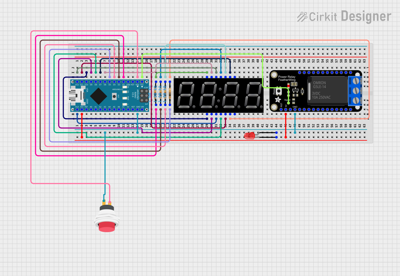
The circuit in question is designed around an Arduino Nano microcontroller and includes an Adafruit PowerRelay Feather Wing, a 5643AS 7-segment display, multiple resistors, a red LED, and a 2-pin push switch. The Arduino Nano controls the 7-segment display and the relay module, while also monitoring a push button to potentially alter the display and relay state. The red LED is connected to the 3.3V power supply through the Arduino Nano and indicates power or status. Resistors are used for current limiting and pull-down purposes.
Component List
Arduino Nano
- Microcontroller board based on the ATmega328P
- It has a variety of digital and analog I/O pins.
Adafruit PowerRelay Feather Wing
- A relay module that allows for controlling high power devices.
5643AS 7-segment display
- A 4-digit 7-segment LED display for showing numerical output.
Resistors (1k Ohms)
- Four resistors each with a resistance of 1000 Ohms, used for current limiting and pull-down configurations.
LED: Two Pin (red)
- A basic red LED for indication purposes.
2Pin Push Switch
- A simple push button switch used to trigger an input on the Arduino Nano.
Wiring Details
Arduino Nano
D13/SCK- Connected to the 7-segment display's decimal point (DP).D12/MISO- Connected to the 7-segment display's segment F.3V3- Powers the red LED and connects to the 3.3V pin on the Adafruit PowerRelay Feather Wing.D11/MOSI- Connected to the 7-segment display's segment G.D10- Connected to the 7-segment display's segment E.D9- Connected to the 7-segment display's segment D.D8- Connected to the 7-segment display's segment C.D7- Connected to the 7-segment display's segment B.GND- Common ground for the LED, push switch, and Adafruit PowerRelay Feather Wing.D6- Connected to the 7-segment display's segment A.D5- Connected to a 1k Ohm resistor.D4- Connected to a 1k Ohm resistor.D3- Connected to a 1k Ohm resistor.D2- Connected to a 1k Ohm resistor.D0/RX- Connected to the push switch's input.D1/TX- Controls the relay on the Adafruit PowerRelay Feather Wing.
Adafruit PowerRelay Feather Wing
RELAY- Controlled by the Arduino Nano'sD1/TXpin.3.3V- Receives power from the Arduino Nano's3V3pin.GND- Connected to the common ground.
5643AS 7-segment display
- Segments and decimal point connected to various digital pins on the Arduino Nano.
D1toD4- Connected to the corresponding pins on the Arduino Nano through 1k Ohm resistors.
Resistors (1k Ohms)
- Each resistor is connected between an Arduino Nano digital pin (
D2toD5) and a corresponding digit pin on the 7-segment display (D1toD4).
LED: Two Pin (red)
cathode- Connected to the Arduino Nano's3V3pin.anode- Connected to the common ground through the push switch.
2Pin Push Switch
Input +- Connected to the Arduino Nano'sD0/RXpin.Output +- Connected to the anode of the red LED and the common ground.
Documented Code
#include <SevSeg.h>

SevSeg sevseg; // Create an instance of the object
#define RELAY 1
#define BUTTON 0

unsigned long previousMillis = 0;
const long interval = 1000; // 1 second
int countdown = 5;
bool relayState = false;

void setup() {
  byte numDigits = 4;
  byte digitPins[] = {2, 3, 4, 5}; // Adjust these pins according to your wiring
  byte segmentPins[] = {6, 7, 8, 9, 10, 11, 12, 13}; // Adjust these pins according to your wiring
  bool resistorsOnSegments = false; // 'false' means resistors are on digit pins
  byte hardwareConfig = COMMON_CATHODE; // or COMMON_ANODE
  bool updateWithDelays = false; // Default 'false' is Recommended
  bool leadingZeros = true; // Use 'true' if you'd like to keep the leading zeros

  sevseg.begin(hardwareConfig, numDigits, digitPins, segmentPins, resistorsOnSegments);
  sevseg.setBrightness(90);

  pinMode(RELAY, OUTPUT);
  pinMode(BUTTON, INPUT_PULLUP);
  sevseg.setNumber(countdown, 0);
}

void loop() {
  unsigned long currentMillis = millis();

  if (digitalRead(BUTTON) == LOW) {
    delay(50); // Debounce delay
    if (digitalRead(BUTTON) == LOW) {
      countdown += 5;
      sevseg.setNumber(countdown, 0);
      while (digitalRead(BUTTON) == LOW); // Wait for button release
    }
  }

  if (countdown > 0 && !relayState) {
    digitalWrite(RELAY, HIGH);
    relayState = true;
  }

  if (currentMillis - previousMillis >= interval) {
    previousMillis = currentMillis;
    if (countdown > 0) {
      countdown--;
      sevseg.setNumber(countdown, 0);
    } else if (relayState) {
      digitalWrite(RELAY, LOW);
      relayState = false;
    }
  }

  sevseg.refreshDisplay(); // Must run repeatedly
}
This code is designed to run on an Arduino Nano and controls a 7-segment display and a relay. It includes a countdown timer that can be incremented by pressing a button. When the countdown is active, the relay is engaged. Once the countdown reaches zero, the relay is disengaged. The display shows the current countdown value, and the button press adds time to the countdown.