Cirkit Designer
Your all-in-one circuit design IDE
Home /
Project Documentation
Arduino Micro-Controlled Wireless Communication System with LCD Interface
Circuit Documentation
Summary
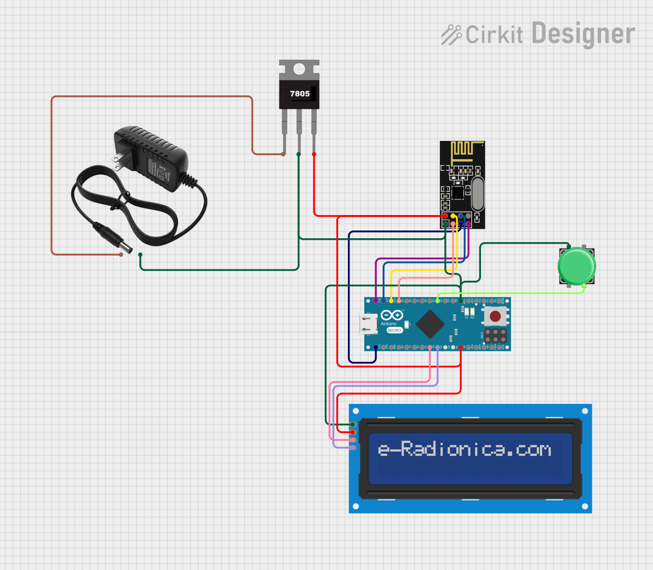
This circuit integrates a variety of components to create a system capable of wireless communication, user interaction, and data display. The core of the circuit is an Arduino Micro (Rev3) microcontroller, which interfaces with an NRF24L01 wireless transceiver module for communication. A 7805 voltage regulator is used to step down the voltage from a 12V power supply to 5V, which powers the microcontroller, the NRF24L01 module, and an LCD screen with I2C interface. A pushbutton is included for user input.
Component List
NRF24L01 Wireless Transceiver Module
- Description: A 2.4GHz wireless transceiver module.
- Pins: IRQ (not used), MOSI, CSN, VCC (3V), GND, CE, SCK, MISO.
Arduino Micro (Rev3)
- Description: A microcontroller board based on the ATmega32U4.
- Pins: MISO, 5V, SCK, MOSI, RESET, GND, RXLED/SS, D1/TX, D0/RX, D2/SDA, D3/SCL, D4 PWM/A6, D5 PWM, D6 PWM/A7, D7, D8 PWM/A8, D9 PWM/A9, D10 PWM/A10, D11 PWM, D12 PWM/A11, VIN, A5, A4, A3, A2, A1, A0, AREF, 3V3, D13 PWM.
7805 Voltage Regulator
- Description: A voltage regulator that outputs a stable 5V from a higher voltage input.
- Pins: Vin, Gnd, Vout.
12V Power Supply
- Description: Provides a 12V voltage source.
- Pins: +, -.
LCD Screen 16x2 I2C
- Description: A 16x2 character LCD display with an I2C interface.
- Pins: SCL, SDA, VCC, GND.
Pushbutton
- Description: A standard pushbutton for user input.
- Pins: Pin 2, Pin 1, Pin 3, Pin 4.
Wiring Details
NRF24L01 Wireless Transceiver Module
- MOSI connected to Arduino Micro D11 PWM
- CSN connected to Arduino Micro D10 PWM/A10
- VCC (3V) connected to 7805 Vout
- GND connected to common ground
- CE connected to Arduino Micro D9 PWM/A9
- SCK connected to Arduino Micro D13 PWM
- MISO connected to Arduino Micro D12 PWM/A11
Arduino Micro (Rev3)
- D11 PWM connected to NRF24L01 MOSI
- D10 PWM/A10 connected to NRF24L01 CSN
- 5V connected to 7805 Vout
- GND connected to common ground
- D9 PWM/A9 connected to NRF24L01 CE
- D13 PWM connected to NRF24L01 SCK
- D12 PWM/A11 connected to NRF24L01 MISO
- D4 PWM/A6 connected to Pushbutton Pin 4
- A5 connected to LCD Screen SCL
- A4 connected to LCD Screen SDA
7805 Voltage Regulator
- Vin connected to 12V Power Supply +
- Gnd connected to common ground
- Vout connected to NRF24L01 VCC (3V), Arduino Micro 5V, and LCD Screen VCC
12V Power Supply
- connected to 7805 Vin
- connected to common ground
LCD Screen 16x2 I2C
- SCL connected to Arduino Micro A5
- SDA connected to Arduino Micro A4
- VCC connected to 7805 Vout
- GND connected to common ground
Pushbutton
- Pin 1 connected to common ground
- Pin 4 connected to Arduino Micro D4 PWM/A6
Documented Code
Arduino Micro (Rev3) - sketch.ino
void setup() {
  // put your setup code here, to run once:

}

void loop() {
  // put your main code here, to run repeatedly:

}
Arduino Micro (Rev3) - documentation.txt
(No additional documentation provided for the code)
This concludes the documentation for the given circuit. The wiring details provide a clear guide for connecting the components, and the code section includes the basic structure for the Arduino Micro (Rev3) microcontroller.