
18650 Li-ion Battery Pack with 4S40A BMS and XL4016 Voltage Regulator for Battery-Powered Applications
View and Edit Project In Cirkit Designer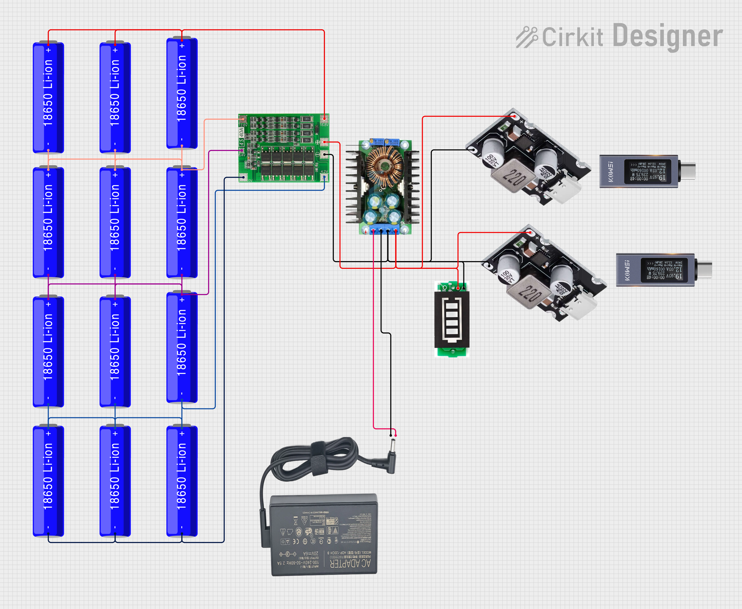
Circuit Documentation
Summary
This document provides a detailed overview of a battery management system (BMS) circuit. The circuit includes multiple 18650 Li-ion batteries, a 4S40A BMS, a battery indicator, an XL4016 voltage regulator, and several chargers. The circuit is designed to manage and monitor the charging and discharging of the batteries, ensuring safe operation and providing status indicators.
Component List
18650 Li-ion Battery
- Description: Rechargeable lithium-ion battery.
- Pins: +, -
4S40A BMS
- Description: Battery management system for 4-series battery packs.
- Pins: 4.2V, -out, +out, 16.8V, 12.6V, 8.4V, -battery
Battery Indicator
- Description: Device to indicate the battery status.
- Pins: +, -
XL4016
- Description: DC-DC buck converter.
- Pins: In+, In-GND, Out-GND, Out+
Cargador
- Description: Charger for the battery pack.
- Pins: 20V, GND
Cargador
- Description: Charger for the battery pack.
- Pins: V+, GND
Probador KWS-2301C tipo C DC 4-30V 0-12A
- Description: Type-C DC tester.
- Pins: None
Wiring Details
18650 Li-ion Battery
Battery 1
- + connected to - of Battery 2
- - connected to - of Battery 3
- - connected to - of Battery 4
- + connected to + of Battery 5
- + connected to 12.6V of 4S40A BMS
- + connected to + of Battery 6
Battery 2
- + connected to + of Battery 3
- + connected to + of Battery 4
- + connected to 16.8V of 4S40A BMS
Battery 3
- + connected to - of Battery 1
- - connected to - of Battery 5
- + connected to + of Battery 7
- + connected to 8.4V of 4S40A BMS
- - connected to - of Battery 6
Battery 4
- - connected to - of Battery 7
- + connected to + of Battery 8
- + connected to + of Battery 9
Battery 5
- - connected to - of Battery 8
- - connected to -battery of 4S40A BMS
- - connected to - of Battery 9
4S40A BMS
- 12.6V connected to + of Battery 1
- 16.8V connected to + of Battery 2
- 8.4V connected to + of Battery 3
- 4.2V connected to + of Battery 4
- -battery connected to - of Battery 5
- -out connected to - of Battery Indicator
- +out connected to + of Battery Indicator
Battery Indicator
- - connected to GND of Cargador
- - connected to Out-GND of XL4016
- - connected to -out of 4S40A BMS
- - connected to GND of Cargador
- + connected to V+ of Cargador
- + connected to Out+ of XL4016
- + connected to +out of 4S40A BMS
- + connected to V+ of Cargador
XL4016
- In+ connected to 20V of Cargador
- In-GND connected to GND of Cargador
- Out-GND connected to - of Battery Indicator
- Out+ connected to + of Battery Indicator
Cargador
- 20V connected to In+ of XL4016
- GND connected to In-GND of XL4016
Cargador
- V+ connected to + of Battery Indicator
- GND connected to - of Battery Indicator
Probador KWS-2301C tipo C DC 4-30V 0-12A
- No connections specified.
Code
No code is provided for this circuit.
This documentation provides a comprehensive overview of the components and their interconnections within the circuit. Each component's role and wiring details are clearly outlined to facilitate understanding and replication of the circuit.