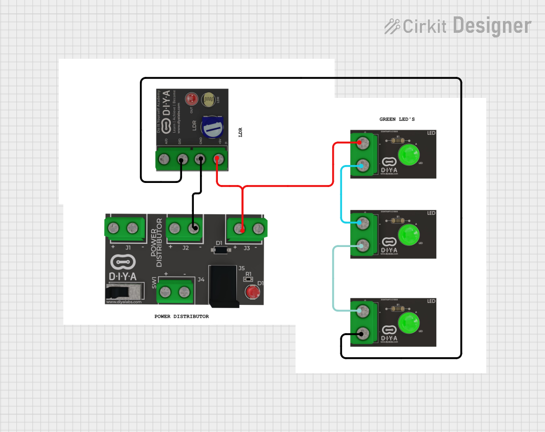
LDR-Controlled LED Lighting System

Circuit Documentation
Summary of the Circuit
The circuit in question appears to be a simple light-detection system that uses a Light Dependent Resistor (LDR) to detect the level of ambient light and control the state of several Green LEDs. The circuit includes a power distribution (Pd) component to supply power to the LDR and LEDs. The LDR has both an analog output (AO) and a digital output (DO), but in this circuit, only the digital output is used to control one of the LEDs directly. The other LEDs are connected in a series configuration and are powered directly by the Pd component.
Component List
Power Distribution (Pd)
- Description: Supplies power to the circuit.
- Pins: Positive(+), Negative(-)
Light Dependent Resistor (LDR)
- Description: Senses the ambient light level.
- Pins: VCC, GND, DO, AO
Green LED
- Description: Indicates the status or level of light detected by the LDR.
- Pins: Negative, Positive
Comments
- Description: Placeholder for additional information or notes about the circuit. These components do not have physical representations or pins.
Wiring Details
Power Distribution (Pd)
- Positive(+) Pin: Connected to the VCC pin of the LDR and the Positive pin of one Green LED.
- Negative(-) Pin: Connected to the GND pin of the LDR.
Light Dependent Resistor (LDR)
- VCC Pin: Connected to the Positive(+) pin of the Pd.
- GND Pin: Connected to the Negative(-) pin of the Pd.
- DO Pin: Connected to the Positive pin of one Green LED.
- AO Pin: Not connected in this circuit.
Green LED 1
- Positive Pin: Connected to the DO pin of the LDR.
- Negative Pin: Not connected in this circuit.
Green LED 2
- Positive Pin: Connected to the Positive(+) pin of the Pd.
- Negative Pin: Connected to the Positive pin of another Green LED.
Green LED 3
- Positive Pin: Connected to the Negative pin of Green LED 2.
- Negative Pin: Connected to the Positive pin of Green LED 1.
Documented Code
There is no code provided for any microcontrollers in this circuit. If the circuit is intended to be controlled by a microcontroller, the code would be necessary to define the behavior of the microcontroller in response to the LDR's output and to control the state of the LEDs. Since no code is provided, it is assumed that the LEDs are controlled directly by the hardware connections without any programmable logic.