
Arduino Nano-Based Wi-Fi Controlled DC Motor System with Limit Switches and Hall Sensors
View and Edit Project In Cirkit Designer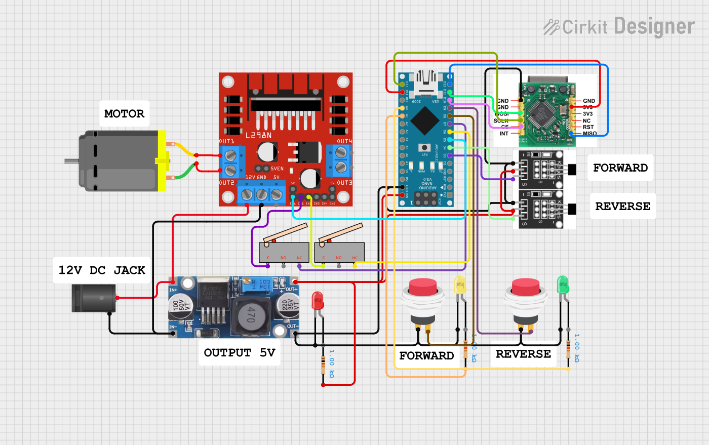
Circuit Documentation
Summary
This document provides a detailed overview of a circuit that includes an Arduino Nano microcontroller, various sensors, switches, LEDs, a motor driver, and other components. The circuit is designed to interface with a DC motor, limit switches, push switches, and a Hall sensor, among other components. The Arduino Nano is programmed to control and monitor these components.
Component List
Arduino Nano
- Description: A small, complete, and breadboard-friendly board based on the ATmega328P.
- Pins: D1/TX, D0/RX, RESET, GND, D2, D3, D4, D5, D6, D7, D8, D9, D10, D11/MOSI, D12/MISO, VIN, 5V, A7, A6, A5, A4, A3, A2, A1, A0, AREF, 3V3, D13/SCK
L298N DC Motor Driver
- Description: A dual H-Bridge motor driver that allows speed and direction control of two DC motors.
- Pins: OUT1, OUT2, 12V, GND, 5V, OUT3, OUT4, 5V-ENA-JMP-I, 5V-ENA-JMP-O, +5V-J1, +5V-J2, ENA, IN1, IN2, IN3, IN4, ENB
W5500 Ethernet Module
- Description: A hardwired TCP/IP embedded Ethernet controller that provides easier internet connection to embedded systems.
- Pins: GND, MOSI, SCLK, CS, 3V, MISO
DC Motor
- Description: A simple DC motor with two connection pins.
- Pins: pin 1, pin 2
2.1mm DC Barrel Jack
- Description: A standard DC power jack for connecting external power supplies.
- Pins: switch, sleeve, center
Limit Switch
- Description: A mechanical switch that can be used to detect the presence or absence of an object.
- Pins: C, NO, NC
LED: Two Pin (Red)
- Description: A standard red LED with two pins.
- Pins: cathode, anode
LED: Two Pin (Yellow)
- Description: A standard yellow LED with two pins.
- Pins: cathode, anode
LED: Two Pin (Green)
- Description: A standard green LED with two pins.
- Pins: cathode, anode
Step Down Buck Converter
- Description: A DC-DC converter that steps down voltage from its input to its output.
- Pins: IN +, IN - GND, OUT +, OUT - GND
Hall Sensor
- Description: A sensor that detects the presence of a magnetic field.
- Pins: -, +, S
2Pin Push Switch
- Description: A simple push-button switch with two connection pins.
- Pins: Input +, Output +
Resistor
- Description: A passive electrical component that provides resistance to the flow of current.
- Pins: pin1, pin2
- Properties: Resistance: 1000 Ohms
Wiring Details
Arduino Nano
- D3 connected to Hall Sensor (S)
- D4 connected to Hall Sensor (S)
- D5 connected to L298N DC Motor Driver (ENA)
- D6 connected to Limit Switch (NC)
- D7 connected to Limit Switch (NC)
- D8 connected to 2Pin Push Switch (Output +)
- D9 connected to 2Pin Push Switch (Output +)
- D10 connected to W5500 (CS)
- D11/MOSI connected to W5500 (MOSI)
- D12/MISO connected to W5500 (MISO)
- VIN connected to Hall Sensor (+), Step Down Buck Converter (OUT +), Resistor (pin2)
- GND connected to 2Pin Push Switch (Input +), LED: Two Pin (Green) (cathode), Hall Sensor (-), Step Down Buck Converter (OUT - GND), LED: Two Pin (Yellow) (cathode), W5500 (GND), LED: Two Pin (Red) (cathode)
- A1 connected to Resistor (pin2)
- A0 connected to Resistor (pin2)
- 3V3 connected to W5500 (3V)
- D13/SCK connected to W5500 (SCLK)
L298N DC Motor Driver
- ENA connected to Arduino Nano (D5)
- OUT1 connected to DC Motor (pin 2)
- OUT2 connected to DC Motor (pin 1)
- 12V connected to 2.1mm DC Barrel Jack (center), Step Down Buck Converter (IN +)
- GND connected to 2.1mm DC Barrel Jack (sleeve), Step Down Buck Converter (IN - GND)
- IN1 connected to Limit Switch (C)
- IN2 connected to Limit Switch (C)
W5500 Ethernet Module
- CS connected to Arduino Nano (D10)
- MOSI connected to Arduino Nano (D11/MOSI)
- MISO connected to Arduino Nano (D12/MISO)
- GND connected to Arduino Nano (GND)
- 3V connected to Arduino Nano (3V3)
- SCLK connected to Arduino Nano (D13/SCK)
DC Motor
- pin 1 connected to L298N DC Motor Driver (OUT2)
- pin 2 connected to L298N DC Motor Driver (OUT1)
2.1mm DC Barrel Jack
- center connected to Step Down Buck Converter (IN +), L298N DC Motor Driver (12V)
- sleeve connected to Step Down Buck Converter (IN - GND), L298N DC Motor Driver (GND)
Limit Switch
- NC connected to Arduino Nano (D6)
- NC connected to Arduino Nano (D7)
- C connected to L298N DC Motor Driver (IN1)
- C connected to L298N DC Motor Driver (IN2)
LED: Two Pin (Red)
- cathode connected to Arduino Nano (GND)
LED: Two Pin (Yellow)
- cathode connected to Arduino Nano (GND)
LED: Two Pin (Green)
- cathode connected to Arduino Nano (GND)
Step Down Buck Converter
- IN + connected to 2.1mm DC Barrel Jack (center), L298N DC Motor Driver (12V)
- IN - GND connected to 2.1mm DC Barrel Jack (sleeve), L298N DC Motor Driver (GND)
- OUT + connected to Arduino Nano (VIN), Hall Sensor (+), Resistor (pin2)
- OUT - GND connected to Arduino Nano (GND), 2Pin Push Switch (Input +), LED: Two Pin (Green) (cathode), Hall Sensor (-), 2Pin Push Switch (Input +), LED: Two Pin (Yellow) (cathode), W5500 (GND), LED: Two Pin (Red) (cathode)
Hall Sensor
- S connected to Arduino Nano (D3)
- S connected to Arduino Nano (D4)
- + connected to Arduino Nano (VIN), Step Down Buck Converter (OUT +), Resistor (pin2)
- - connected to Arduino Nano (GND), Step Down Buck Converter (OUT - GND)
2Pin Push Switch
- Output + connected to Arduino Nano (D8)
- Output + connected to Arduino Nano (D9)
- Input + connected to Arduino Nano (GND), LED: Two Pin (Green) (cathode), Hall Sensor (-), Step Down Buck Converter (OUT - GND), LED: Two Pin (Yellow) (cathode), W5500 (GND), LED: Two Pin (Red) (cathode)
Resistor
- pin2 connected to Arduino Nano (VIN), Hall Sensor (+), Step Down Buck Converter (OUT +)
- pin2 connected to Arduino Nano (A1)