
Battery-Powered LM393-Based Voltage Comparator Circuit with MOSFET Control
View and Edit Project In Cirkit Designer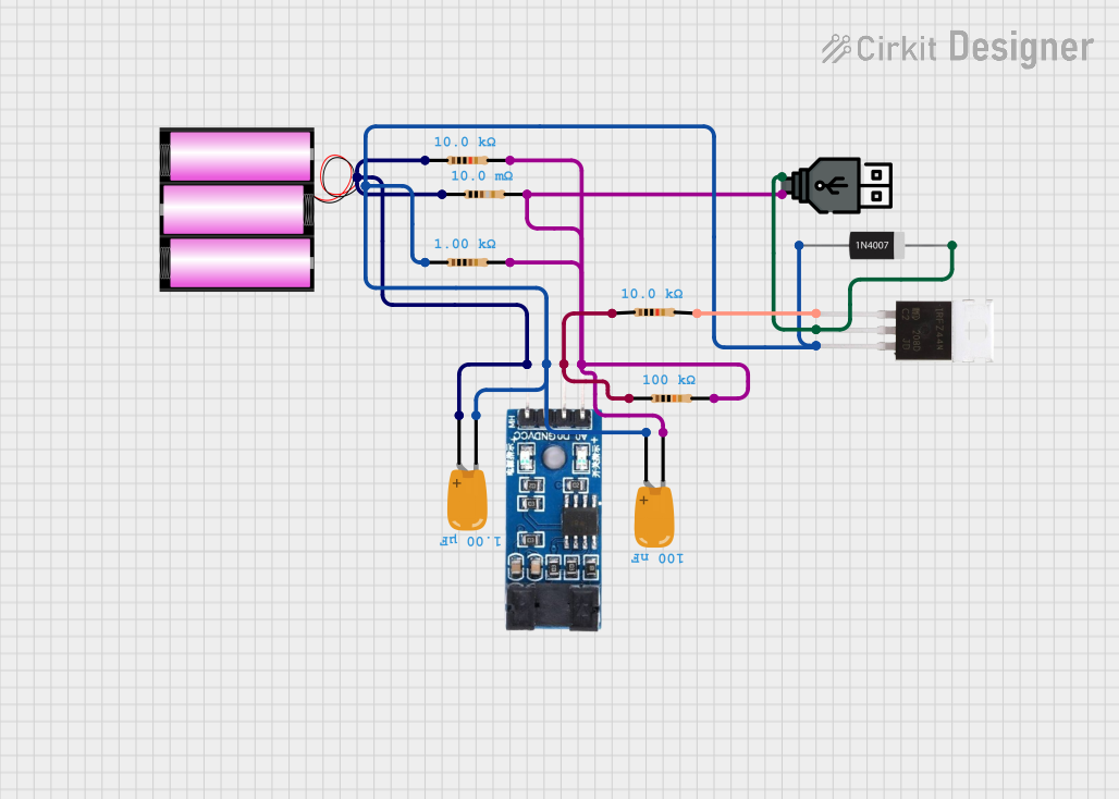
Circuit Documentation
Summary
This document provides a detailed overview of a circuit design that includes various components such as resistors, capacitors, a MOSFET, a diode, a comparator, and power sources. The circuit is designed to perform specific functions by interconnecting these components through defined electrical nets.
Component List
Resistor
- Description: A passive electrical component that implements electrical resistance as a circuit element.
- Pins: pin1, pin2
- Properties:
- Resistance: 100 kOhms
- Resistance: 10 kOhms
- Resistance: 0.01 Ohms
- Resistance: 1 kOhms
- Resistance: 10 kOhms
Battery 12V
- Description: A 12-volt battery used as a power source.
- Pins: +, -
IRFZ44N (MOSFET)
- Description: A type of MOSFET used for switching and amplifying electronic signals.
- Pins: Gate, Drain, Source
Tantalum Capacitor
- Description: A type of electrolytic capacitor, a passive component that stores energy in an electric field.
- Pins: -, +
- Properties:
- Capacitance: 100 nF
- Capacitance: 1 µF
1N4007 Rectifier Diode
- Description: A diode used for rectification, converting AC to DC.
- Pins: Cathode, Anode
USB Power
- Description: A power source providing USB standard voltage.
- Pins: +, -
LM393 (Comparator)
- Description: A dual comparator IC used for comparing voltages.
- Pins: VCC, GND, D0, A0
Wiring Details
Resistor (100 kOhms)
- pin1: Connected to LM393 (D0) and another Resistor (10 kOhms)
- pin2: Connected to Tantalum Capacitor (-), LM393 (A0), multiple Resistors, and USB power (+)
Resistor (10 kOhms)
- pin1: Connected to LM393 (D0) and another Resistor (100 kOhms)
- pin2: Connected to Tantalum Capacitor (-), LM393 (A0), multiple Resistors, and USB power (+)
Resistor (0.01 Ohms)
- pin1: Connected to Tantalum Capacitor (+), LM393 (VCC), multiple Resistors, and battery 12V (+)
- pin2: Connected to Tantalum Capacitor (-), LM393 (A0), multiple Resistors, and USB power (+)
Resistor (1 kOhms)
- pin1: Connected to Tantalum Capacitor (+), LM393 (VCC), multiple Resistors, and battery 12V (+)
- pin2: Connected to Tantalum Capacitor (-), LM393 (A0), multiple Resistors, and USB power (+)
Resistor (10 kOhms)
- pin1: Connected to Tantalum Capacitor (+), LM393 (VCC), multiple Resistors, and battery 12V (+)
- pin2: Connected to IRFZ44N (Gate)
Battery 12V
- +: Connected to Tantalum Capacitor (+), LM393 (VCC), multiple Resistors
- -: Connected to Tantalum Capacitor (+), LM393 (GND), multiple Resistors, and IRFZ44N (Source)
IRFZ44N (MOSFET)
- Gate: Connected to Resistor (10 kOhms)
- Drain: Connected to 1N4007 Rectifier Diode (Cathode) and USB power (-)
- Source: Connected to Tantalum Capacitor (+), LM393 (GND), multiple Resistors, and battery 12V (-)
Tantalum Capacitor (100 nF)
- -: Connected to LM393 (A0), multiple Resistors, and USB power (+)
- +: Connected to Tantalum Capacitor (+), LM393 (VCC), multiple Resistors, and battery 12V (+)
Tantalum Capacitor (1 µF)
- -: Connected to LM393 (A0), multiple Resistors, and USB power (+)
- +: Connected to Tantalum Capacitor (+), LM393 (VCC), multiple Resistors, and battery 12V (+)
1N4007 Rectifier Diode
- Cathode: Connected to USB power (-) and IRFZ44N (Drain)
- Anode: Connected to Tantalum Capacitor (+), LM393 (GND), multiple Resistors, and battery 12V (-)
USB Power
- +: Connected to Tantalum Capacitor (-), LM393 (A0), multiple Resistors
- -: Connected to 1N4007 Rectifier Diode (Cathode) and IRFZ44N (Drain)
LM393 (Comparator)
- VCC: Connected to Tantalum Capacitor (+), multiple Resistors, and battery 12V (+)
- GND: Connected to Tantalum Capacitor (+), multiple Resistors, and battery 12V (-)
- D0: Connected to Resistor (100 kOhms) and another Resistor (10 kOhms)
- A0: Connected to Tantalum Capacitor (-), multiple Resistors, and USB power (+)
Code
No microcontroller code is provided for this circuit.
This document provides a comprehensive overview of the circuit, including a detailed list of components and their interconnections. This should serve as a useful reference for understanding and troubleshooting the circuit.