Arduino UNO Solar-Powered Light Sensor System with Servo Control
Circuit Documentation
Summary
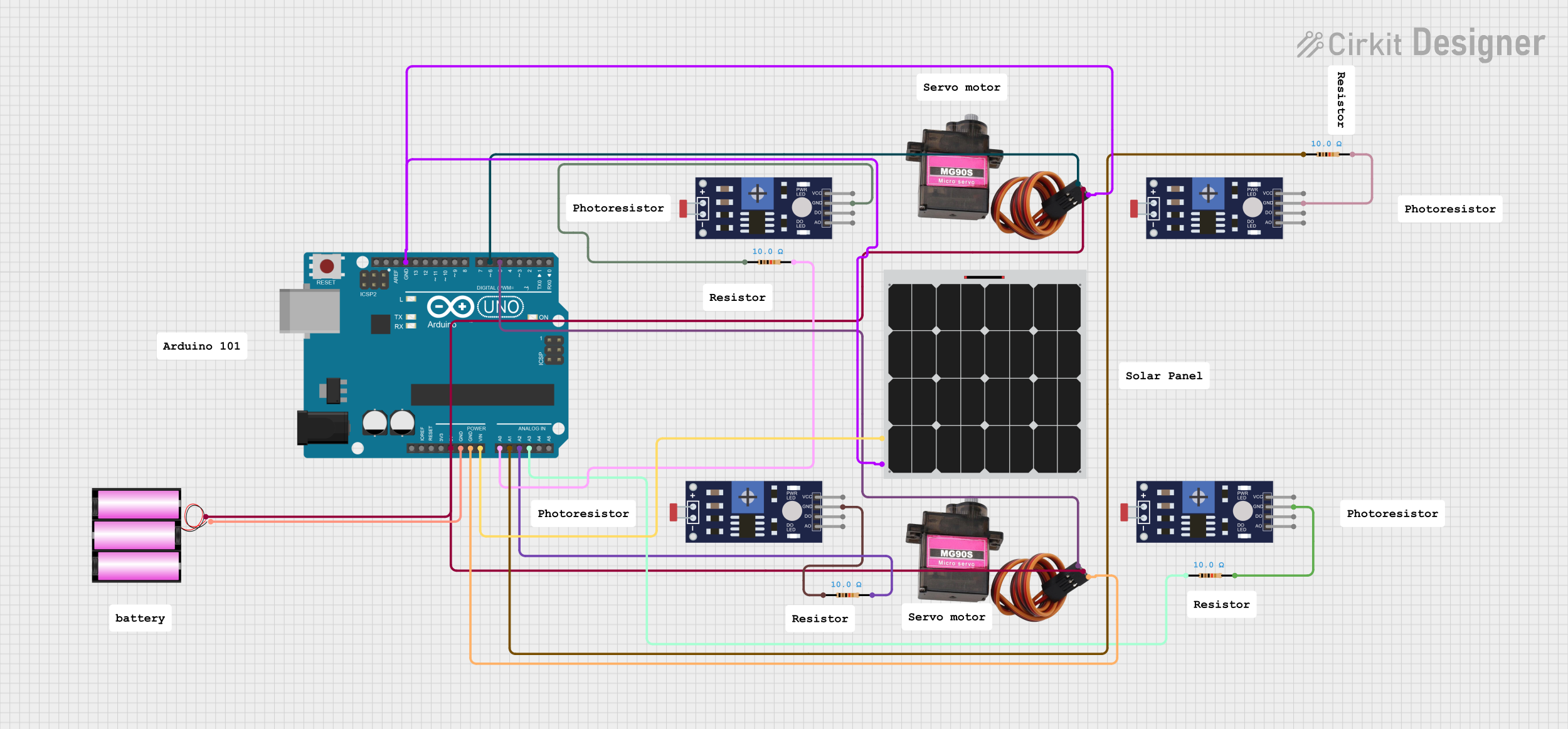
This circuit involves a combination of photoresistor sensors, resistors, a solar panel, a battery, and an Arduino UNO microcontroller. The circuit is designed to measure light intensity using photoresistors and control two MG90S servos based on the readings. The Arduino UNO is powered by a 12V battery and a solar panel, and it reads the analog signals from the photoresistors to control the servos.
Component List
Battery 12V
- Pins: +, -
- Description: Provides 12V power supply to the circuit.
Photoresistor (LDR) Sensor (Wokwi Compatible)
- Pins: VCC, GND, DO, AO
- Description: Measures light intensity.
Resistor
- Pins: pin1, pin2
- Description: Limits current in the circuit.
- Properties: Resistance: 10 Ohms
Solar Panel
- Pins: +, -
- Description: Provides additional power supply to the circuit.
MG90S Servo Motor
- Pins: SIG, VCC, GND
- Description: Controls mechanical movement.
Arduino UNO
- Pins: UNUSED, IOREF, Reset, 3.3V, 5V, GND, Vin, A0, A1, A2, A3, A4, A5, SCL, SDA, AREF, D13, D12, D11, D10, D9, D8, D7, D6, D5, D4, D3, D2, D1, D0
- Description: Microcontroller for processing and control.
Wiring Details
Battery 12V
+ Pin:
- Connected to Arduino UNO (5V)
- Connected to MG90S Servo Motor (VCC)
- Connected to MG90S Servo Motor (VCC)
- Pin:
- Connected to Arduino UNO (GND)
Photoresistor (LDR) Sensor (Wokwi Compatible)
Instance 1:
- GND Pin: Connected to Resistor (pin1)
Instance 2:
- GND Pin: Connected to Resistor (pin1)
Instance 3:
- GND Pin: Connected to Resistor (pin2)
Instance 4:
- GND Pin: Connected to Resistor (pin2)
Resistor
Instance 1:
- pin1: Connected to Photoresistor (GND)
- pin2: Connected to Arduino UNO (A2)
Instance 2:
- pin1: Connected to Photoresistor (GND)
- pin2: Connected to Arduino UNO (A0)
Instance 3:
- pin1: Connected to Photoresistor (GND)
- pin2: Connected to Arduino UNO (A1)
Instance 4:
- pin1: Connected to Photoresistor (GND)
- pin2: Connected to Arduino UNO (A3)
Solar Panel
+ Pin:
- Connected to Arduino UNO (Vin)
- Pin:
- Connected to Arduino UNO (GND)
- Connected to MG90S Servo Motor (GND)
MG90S Servo Motor
Instance 1:
- SIG Pin: Connected to Arduino UNO (D5)
- VCC Pin: Connected to Battery 12V (+)
- GND Pin: Connected to Arduino UNO (GND)
Instance 2:
- SIG Pin: Connected to Arduino UNO (D6)
- VCC Pin: Connected to Battery 12V (+)
- GND Pin: Connected to Solar Panel (-)
Arduino UNO
- 5V Pin: Connected to Battery 12V (+)
- GND Pin: Connected to Battery 12V (-)
- A2 Pin: Connected to Resistor (pin2)
- A1 Pin: Connected to Resistor (pin2)
- A0 Pin: Connected to Resistor (pin2)
- A3 Pin: Connected to Resistor (pin2)
- Vin Pin: Connected to Solar Panel (+)
- D5 Pin: Connected to MG90S Servo Motor (SIG)
- D6 Pin: Connected to MG90S Servo Motor (SIG)
Code Documentation
Arduino UNO Code
void setup() {
  // put your setup code here, to run once:

}

void loop() {
  // put your main code here, to run repeatedly:

}
This code is a basic template for the Arduino UNO. The setup() function is where you initialize your settings, and the loop() function is where the main code runs repeatedly. You can add your specific logic to control the servos based on the readings from the photoresistors in these functions.