
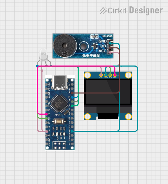
Circuit Documentation
Summary
This document provides a detailed overview of a circuit that includes a Nano 3.0 ATmega328P microcontroller, a buzzer module, an OLED display, and an RGB LED. The circuit is designed to interface these components with the microcontroller to perform various functions such as displaying information, generating sound, and emitting colored light.
Component List
Buzzer Module
- Description: A module used to generate sound.
- Pins: GND, Vcc, I/O
Nano 3.0 ATmega328P Type-C USB CH340 Controller Board
- Description: A microcontroller board based on the ATmega328P, equipped with a Type-C USB interface and CH340 USB-to-serial chip.
- Pins: D13, 3V3, REF, A0, A1, A2, A3, A4, A5, A6, A7, 5V, RST, GND, VIN, D11, D10, D9, D8, D7, D6, D5, D4, D3, D2, RX0, TX1, D12
OLED 128x64 I2C Monochrome Display VDD-GND
- Description: A monochrome OLED display with a resolution of 128x64 pixels, interfaced via I2C.
- Pins: VDD, GND, SCK, SDA
RGB LED (Wokwi compatible)
- Description: An RGB LED that can emit red, green, and blue light.
- Pins: R, COM, G, B
Wiring Details
Buzzer Module
- GND connected to GND of Nano 3.0 ATmega328P
- Vcc connected to 5V of Nano 3.0 ATmega328P
- I/O connected to D10 of Nano 3.0 ATmega328P
Nano 3.0 ATmega328P Type-C USB CH340 Controller Board
- GND connected to GND of Buzzer Module and OLED Display
- 5V connected to Vcc of Buzzer Module, COM of RGB LED, and VDD of OLED Display
- D10 connected to I/O of Buzzer Module
- A4 connected to SDA of OLED Display
- A5 connected to SCK of OLED Display
- D9 connected to R of RGB LED
- D8 connected to G of RGB LED
- D7 connected to B of RGB LED
OLED 128x64 I2C Monochrome Display VDD-GND
- GND connected to GND of Nano 3.0 ATmega328P
- VDD connected to 5V of Nano 3.0 ATmega328P
- SCK connected to A5 of Nano 3.0 ATmega328P
- SDA connected to A4 of Nano 3.0 ATmega328P
RGB LED (Wokwi compatible)
- R connected to D9 of Nano 3.0 ATmega328P
- COM connected to 5V of Nano 3.0 ATmega328P
- G connected to D8 of Nano 3.0 ATmega328P
- B connected to D7 of Nano 3.0 ATmega328P
Code
No code is provided for this circuit.
This document provides a comprehensive overview of the circuit, including a summary, detailed component list, wiring details, and code documentation. This should serve as a useful reference for understanding and replicating the circuit.