Arduino UNO Based Heart Rate Monitor with OLED Display
Circuit Documentation
Summary of the Circuit
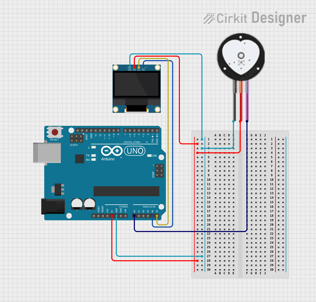
This circuit consists of an Arduino UNO microcontroller, a Heart Pulse Sensor, and a 0.96" OLED display. The Arduino UNO serves as the central processing unit, interfacing with the Heart Pulse Sensor to read pulse data and with the OLED display to output information. The Heart Pulse Sensor detects the heartbeat of a user, and the OLED display provides a visual output. The circuit is powered by the Arduino UNO's 5V output, which is distributed to the other components. Ground connections are shared among all components to complete the circuit.
Component List
Arduino UNO
- Description: A microcontroller board based on the ATmega328P.
- Pins Used:
IOREFReset3.3V5VGNDVinA0toA5SCLSDAAREFD13toD0
Heart Pulse Sensor
- Description: A sensor that measures the heartbeat of a user.
- Pins Used:
GNDVCCSIGNAL
0.96" OLED
- Description: A small OLED display for visual output.
- Pins Used:
GNDVDDSCKSDA
Wiring Details
Arduino UNO
GNDconnected to the common ground net.5Vconnected to the VCC net, providing power to the Heart Pulse Sensor and OLED display.A0connected to theSIGNALpin of the Heart Pulse Sensor for reading pulse data.A4(SDA) connected to theSDApin of the OLED display for I2C data communication.A5(SCL) connected to theSCKpin of the OLED display for I2C clock signal.
Heart Pulse Sensor
GNDconnected to the common ground net.VCCconnected to the 5V power net from the Arduino UNO.SIGNALconnected to theA0pin of the Arduino UNO for pulse signal output.
0.96" OLED
GNDconnected to the common ground net.VDDconnected to the 5V power net from the Arduino UNO.SDAconnected to theA4(SDA) pin of the Arduino UNO for I2C data communication.SCKconnected to theA5(SCL) pin of the Arduino UNO for I2C clock signal.
Documented Code
Arduino UNO Code (sketch.ino)
void setup() {
  // put your setup code here, to run once:

}

void loop() {
  // put your main code here, to run repeatedly:

}
Note: The provided code is a template and does not contain any functional code for operating the Heart Pulse Sensor or the OLED display. The user is expected to write the necessary setup and loop code to initialize the I2C communication, read data from the Heart Pulse Sensor, and display the results on the OLED.