Cirkit Designer
Your all-in-one circuit design IDE
Home /
Project Documentation
Arduino UNO-Based Automated Watering System with Water Level Sensors and Relays
Circuit Documentation
Summary
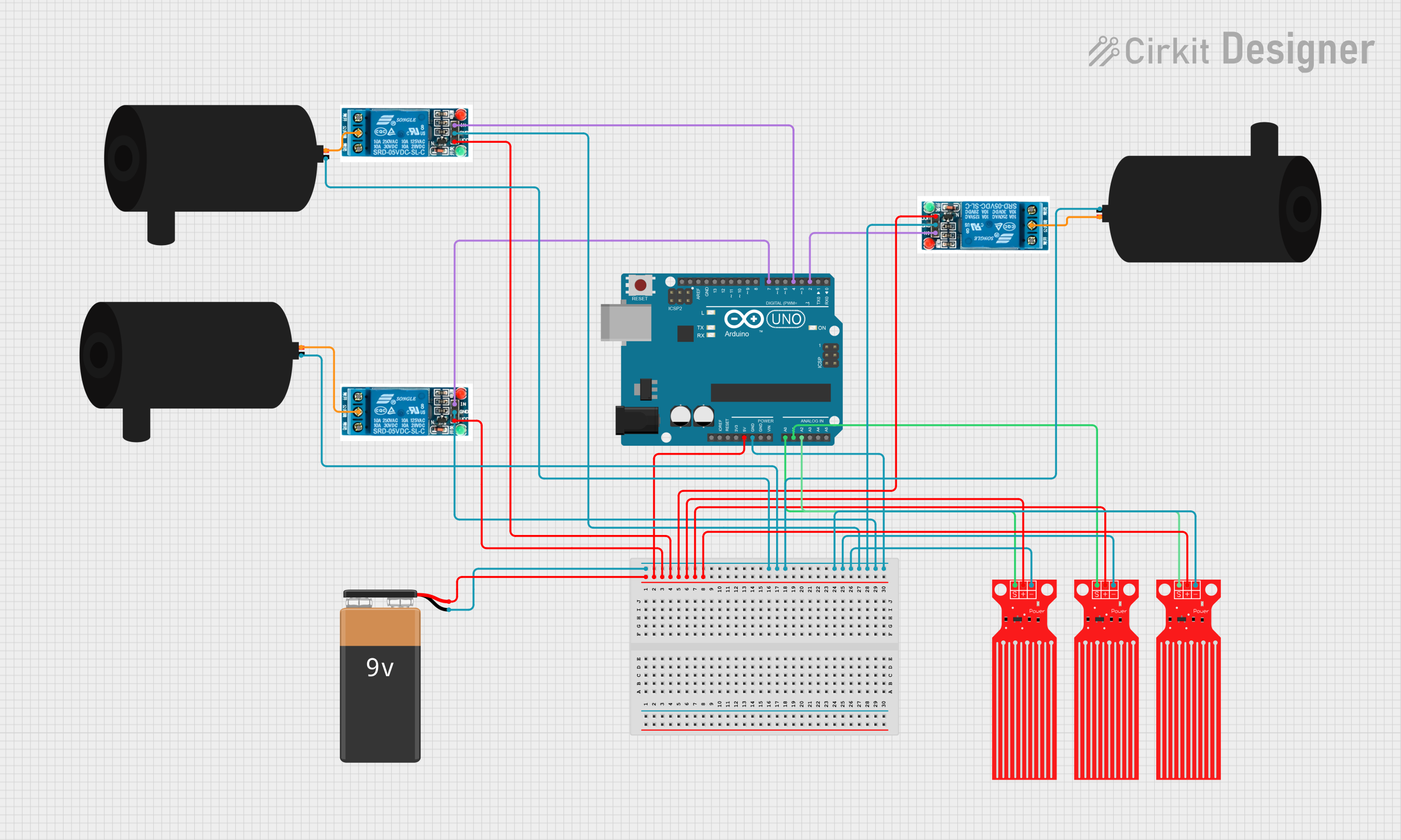
This circuit is designed to control water pumps for an artificial flower setup using an Arduino UNO. The system includes water level sensors to monitor the water levels and relays to control the pumps. The Arduino UNO reads the sensor data and activates the pumps at regular intervals to dispense water.
Component List
Water Level Sensor
- Description: Measures the water level in a container.
- Pins: SIG, VCC, GND
Arduino UNO
- Description: Microcontroller board used to control the circuit.
- Pins: UNUSED, IOREF, Reset, 3.3V, 5V, GND, Vin, A0, A1, A2, A3, A4, A5, SCL, SDA, AREF, D13, D12, D11, D10, D9, D8, D7, D6, D5, D4, D3, D2, D1, D0
Water Pump
- Description: Pumps water to the artificial flowers.
- Pins: positive, negative
5V Relay
- Description: Controls the water pumps based on signals from the Arduino.
- Pins: Normally Open, Common terminal, Normally Closed, In, GND, VCC
9V Battery
- Description: Provides power to the circuit.
- Pins: +, -
Wiring Details
Water Level Sensor
- VCC connected to 5V on the Arduino UNO.
- GND connected to GND on the Arduino UNO.
- SIG connected to:
- A1 on the Arduino UNO for the first sensor.
- A0 on the Arduino UNO for the second sensor.
- A2 on the Arduino UNO for the third sensor.
Arduino UNO
- 5V connected to + on the 9V Battery.
- GND connected to - on the 9V Battery.
- D7 connected to In on the first 5V Relay.
- D4 connected to In on the second 5V Relay.
- D2 connected to In on the third 5V Relay.
Water Pump
- positive connected to Common terminal on the corresponding 5V Relay.
- negative connected to - on the 9V Battery.
5V Relay
- VCC connected to 5V on the Arduino UNO.
- GND connected to GND on the Arduino UNO.
- Common terminal connected to positive on the corresponding Water Pump.
9V Battery
- + connected to 5V on the Arduino UNO.
- - connected to GND on the Arduino UNO.
Documented Code
// Pin Definitions
const int flower1PumpRelayPin = 2;    // Relay for pump 1 (Artificial Flower 1)
const int flower2PumpRelayPin = 3;    // Relay for pump 2 (Artificial Flower 2)

// Timing Variables
unsigned long previousTimeFlower1 = 0;  // Last time flower 1 pump was activated
unsigned long previousTimeFlower2 = 0;  // Last time flower 2 pump was activated
const unsigned long interval = 10000;   // 10 seconds interval for nectar dispensing

void setup() {
  // Set pump relay pins as OUTPUT
  pinMode(flower1PumpRelayPin, OUTPUT);
  pinMode(flower2PumpRelayPin, OUTPUT);

  // Initialize relays to OFF state (HIGH for active-low relays)
  digitalWrite(flower1PumpRelayPin, HIGH);
  digitalWrite(flower2PumpRelayPin, HIGH);
}

void loop() {
  // Get the current time in milliseconds
  unsigned long currentTime = millis();

  // Flower 1: Check if 10 seconds have passed since the last nectar dispense
  if (currentTime - previousTimeFlower1 >= interval) {
    previousTimeFlower1 = currentTime;  // Update the last dispensing time

    // Turn on the pump for Flower 1 briefly to release a drop
    digitalWrite(flower1PumpRelayPin, LOW); // Turn ON pump for Flower 1
    delay(300);                             // Pump runs for 300ms
    digitalWrite(flower1PumpRelayPin, HIGH); // Turn OFF pump for Flower 1
  }

  // Flower 2: Check if 10 seconds have passed since the last nectar dispense
  if (currentTime - previousTimeFlower2 >= interval) {
    previousTimeFlower2 = currentTime;  // Update the last dispensing time

    // Turn on the pump for Flower 2 briefly to release a drop
    digitalWrite(flower2PumpRelayPin, LOW); // Turn ON pump for Flower 2
    delay(300);                             // Pump runs for 300ms
    digitalWrite(flower2PumpRelayPin, HIGH); // Turn OFF pump for Flower 2
  }
}
This code sets up the Arduino to control two water pumps, each connected to a relay. The pumps are activated every 10 seconds to dispense water for a brief period. The relays are controlled using digital pins on the Arduino, and the timing is managed using the millis() function to ensure non-blocking delays.