
Wi-Fi Enabled Load Cell Measurement System with Arduino Mega and ESP8266
View and Edit Project In Cirkit Designer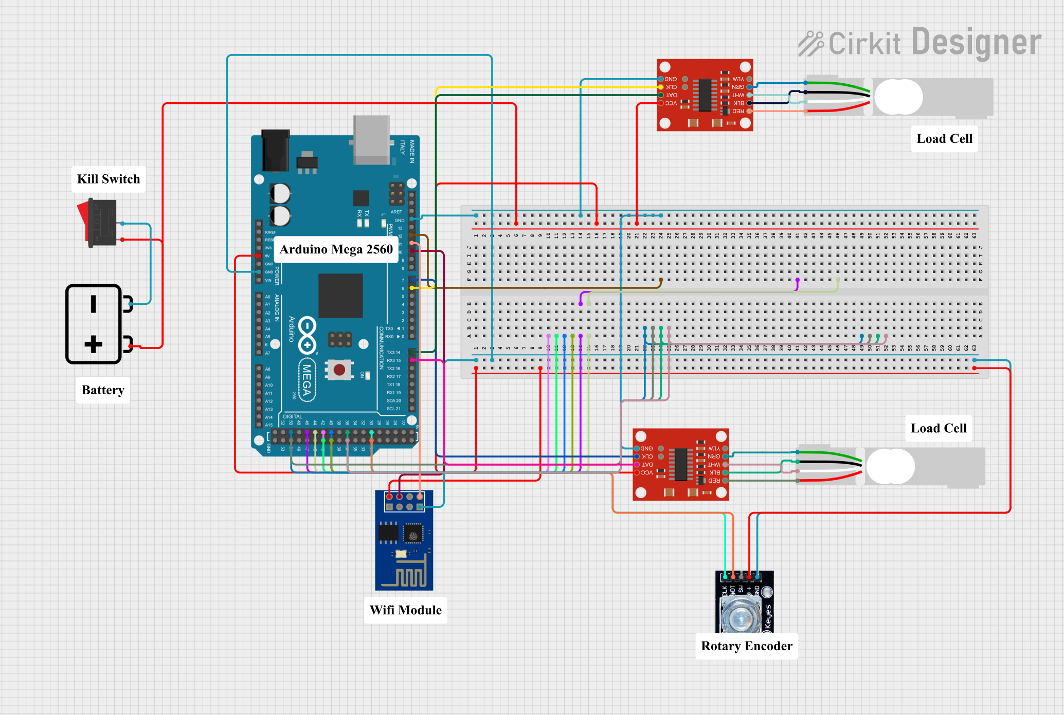
Circuit Documentation
Summary
This circuit involves multiple components including load cells, a rocker switch, a 12V battery, load cell amplifiers, an ESP8266 WiFi module, an Arduino Mega 2560, and a rotary encoder. The circuit is designed to measure weight using load cells, amplify the signal using HX711 load cell amplifiers, and transmit data wirelessly using the ESP8266 module. The Arduino Mega 2560 serves as the main microcontroller, coordinating the activities of the other components.
Component List
Load Cell - Red/white/black/green
- Description: A load cell used for measuring weight.
- Pins: E+, A-, E-, A+
Rocker Switch
- Description: A simple on/off switch.
- Pins: 1, 2
12V Battery
- Description: A power source for the circuit.
- Pins: +, -
SparkFun Load Cell Amplifier - HX711
- Description: An amplifier for load cell signals.
- Pins: GND, CLK, DAT, VCC, YLW, GRN, WHT, BLK, RED, B-, B+
ESP8266 ESP-01 WiFi Module
- Description: A WiFi module for wireless communication.
- Pins: TXD, CH_PD, RST, VCC, GND, GPIO_2, GPIO_0, RXD
Arduino Mega 2560
- Description: A microcontroller board based on the ATmega2560.
- Pins: IOREF, RESET, 3V3, 5V, GND, VIN, A0-A15, D0-D53, PWM pins, AREF, SDA, SCL
Rotary Encoder
- Description: A rotary encoder for user input.
- Pins: clk, dt, sw, gnd, +
Wiring Details
Load Cell - Red/white/black/green
- E+ connected to RED on SparkFun Load Cell Amplifier - HX711
- A- connected to WHT on SparkFun Load Cell Amplifier - HX711
- E- connected to BLK on SparkFun Load Cell Amplifier - HX711
- A+ connected to GRN on SparkFun Load Cell Amplifier - HX711
Rocker Switch
- Pin 1 connected to + on 12V Battery
- Pin 2 connected to - on 12V Battery
12V Battery
- + connected to Pin 1 on Rocker Switch
- - connected to Pin 2 on Rocker Switch
SparkFun Load Cell Amplifier - HX711
- GND connected to GND on Arduino Mega 2560
- CLK connected to D7 PWM on Arduino Mega 2560
- DAT connected to D15/RX3 on Arduino Mega 2560
- VCC connected to Pin 1 on Rocker Switch
- RED connected to E+ on Load Cell
- WHT connected to A- on Load Cell
- BLK connected to E- on Load Cell
- GRN connected to A+ on Load Cell
ESP8266 ESP-01 WiFi Module
- VCC connected to 5V on Arduino Mega 2560
- GND connected to GND on Arduino Mega 2560
- TXD connected to D11 PWM on Arduino Mega 2560
- RST connected to D10 PWM on Arduino Mega 2560
Arduino Mega 2560
- 5V connected to VCC on ESP8266 ESP-01 WiFi Module and + on Rotary Encoder
- GND connected to GND on ESP8266 ESP-01 WiFi Module, GND on Rotary Encoder, and GND on SparkFun Load Cell Amplifier - HX711
- D7 PWM connected to CLK on SparkFun Load Cell Amplifier - HX711
- D15/RX3 connected to DAT on SparkFun Load Cell Amplifier - HX711
- D11 PWM connected to TXD on ESP8266 ESP-01 WiFi Module
- D10 PWM connected to RST on ESP8266 ESP-01 WiFi Module
- D30 connected to clk on Rotary Encoder
- D31 connected to dt on Rotary Encoder
Rotary Encoder
- + connected to 5V on Arduino Mega 2560
- gnd connected to GND on Arduino Mega 2560
- clk connected to D30 on Arduino Mega 2560
- dt connected to D31 on Arduino Mega 2560
Documented Code
Arduino Mega 2560 Code
void setup() {
  // put your setup code here, to run once:

}

void loop() {
  // put your main code here, to run repeatedly:

}
This code is a basic template for the Arduino Mega 2560. The setup function is used to initialize any settings or configurations, and the loop function contains the main code that runs repeatedly.