
Arduino Nano Based GPS Tracker with GSM Capability and Power Management
View and Edit Project In Cirkit Designer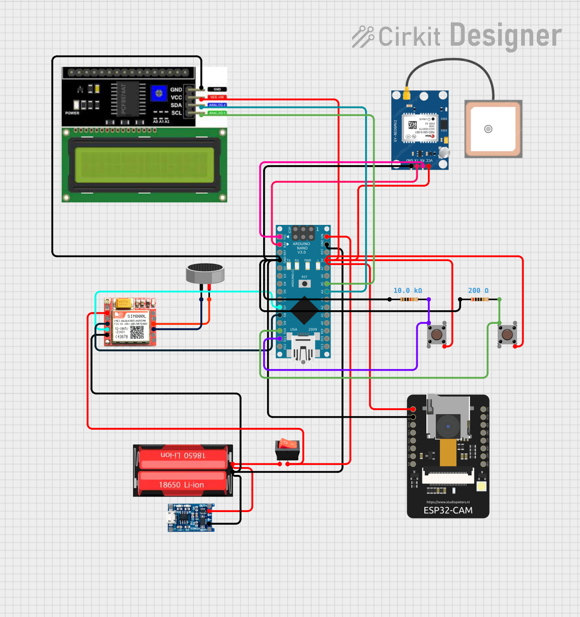
Circuit Documentation
Summary
This circuit integrates various components including an Arduino Nano, GPS module, Li-Ion battery, pushbuttons, an LCD I2C display, a TP4056 charging module, a rocker switch, a condenser microphone, a SIM800L GSM module, resistors, and an ESP32-CAM module. The Arduino Nano serves as the central microcontroller, interfacing with the GPS module for location tracking, the SIM800L for GSM communication, and the LCD display for user interface. The ESP32-CAM provides camera functionality. The circuit is powered by a 18650 Li-Ion battery, with charging managed by the TP4056 module. User inputs are captured through pushbuttons, and the rocker switch controls power flow. The microphone interfaces with the SIM800L for audio input.
Component List
- Arduino Nano: A compact microcontroller board based on the ATmega328P, featuring digital and analog I/O pins.
- GPS NEO 6M: A GPS module for satellite navigation.
- 18650 Li-Ion Battery: A rechargeable lithium-ion cell used for powering the circuit.
- Pushbutton: A momentary switch used for user input.
- LCD I2C Display: A liquid crystal display with an I2C interface for showing information.
- TP4056 Charging Module: A module used for charging lithium-ion batteries.
- Rocker Switch: A switch used to control the power supply to the circuit.
- Condenser Microphone: An audio input device for capturing sound.
- SIM800L: A GSM module for cellular communication.
- Resistor: A passive component used to limit current or divide voltages.
- ESP32-CAM: A camera module with Wi-Fi capabilities.
Wiring Details
Arduino Nano
D1/TXconnected to GPS NEO 6MRXD0/RXconnected to GPS NEO 6MTXGNDconnected to common ground netD7connected to SIM800LTXDD8connected to SIM800LRXDD10connected to Pushbutton (ID: 258f6b97-56dc-4bb4-a24c-b3fec3b767ed)Pin 1 (in)D11/MOSIconnected to Pushbutton (ID: 17e092d1-9d2d-4e56-a79f-d55259af42df)Pin 1 (in)VINconnected to rocker switchoutput5Vconnected to common VCC netA5connected to LCD I2C DisplaySCLA4connected to LCD I2C DisplaySDA
GPS NEO 6M
VCCconnected to common VCC netRXconnected to Arduino NanoD1/TXTXconnected to Arduino NanoD0/RXGNDconnected to common ground net
18650 Li-Ion Battery
Positiveconnected to TP4056 Charging Module and rocker switchinputNegativeconnected to common ground net
Pushbuttons
Pin 1 (in)connected to Arduino NanoD10orD11/MOSIvia respective resistorsPin 4 (out)connected to common VCC net
LCD I2C Display
GNDconnected to common ground netVCCconnected to common VCC netSDAconnected to Arduino NanoA4SCLconnected to Arduino NanoA5
TP4056 Charging Module
- Connected to 18650 Li-Ion Battery and common ground net
Rocker Switch
outputconnected to Arduino NanoVINinputconnected to 18650 Li-Ion BatteryPositive
Condenser Microphone
pin1connected to SIM800LMIC-pin2connected to SIM800LMIC +
SIM800L
VCCconnected to Arduino NanoVINTXDconnected to Arduino NanoD7RXDconnected to Arduino NanoD8GNDconnected to common ground netMIC +connected to Condenser Microphonepin2MIC-connected to Condenser Microphonepin1
Resistors
- Connected between Arduino Nano
GNDand pushbuttonsPin 1 (in)
ESP32-CAM
GNDconnected to common ground net5Vconnected to common VCC net
Documented Code
Arduino Nano Code (sketch.ino)
void setup() {
  // put your setup code here, to run once:

}

void loop() {
  // put your main code here, to run repeatedly:

}
Note: The code provided for the Arduino Nano is a template and does not contain any functional code specific to the circuit's operation. It will need to be populated with the appropriate setup and loop functions to control the connected components.