Arduino-Controlled Dual IR Sensor DC Motor Driver
Circuit Documentation
Summary
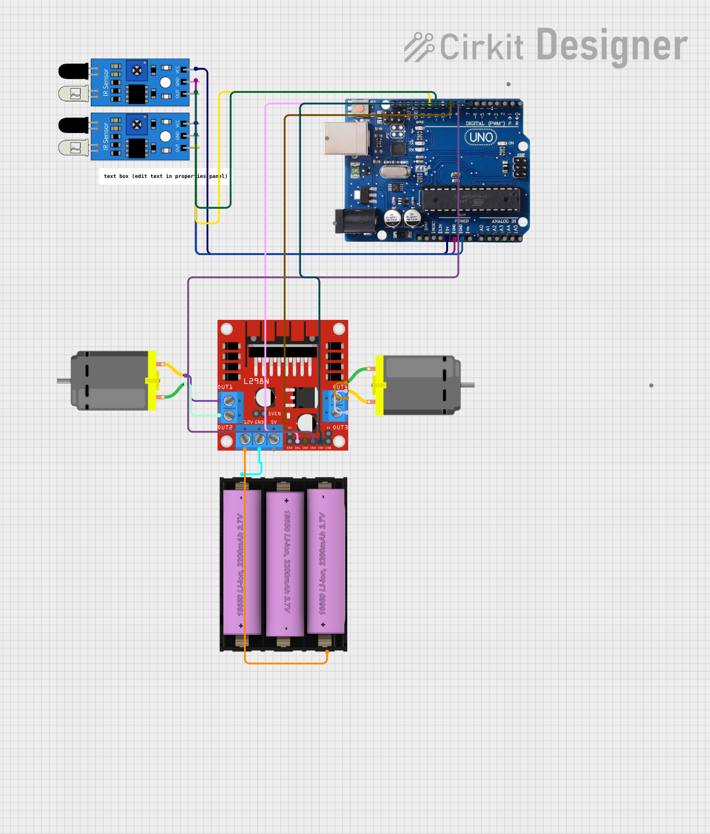
The circuit in question is designed to interface an Arduino Uno R3 with two IR sensors and two DC motors through an L298N DC motor driver. The Arduino Uno R3 serves as the central control unit, providing power to the IR sensors and control signals to the L298N motor driver, which in turn controls the DC motors. A Li-ion battery supplies power to the motor driver, which powers the motors. The IR sensors are used for input sensing, and their outputs are connected to the Arduino for processing.
Component List
Arduino Uno R3
- Microcontroller board based on the ATmega328P
- It has 14 digital input/output pins, 6 analog inputs, a USB connection, a power jack, an ICSP header, and a reset button.
IR Sensor (2 units)
- An infrared sensor capable of detecting obstacles and measuring distances.
- It has three pins: VCC, GND, and an output signal pin.
DC Motor (2 units)
- An electric motor that converts electrical energy into mechanical energy.
- It has two connection pins for power and control.
L298N DC Motor Driver
- A dual H-bridge motor driver that can drive two DC motors or one stepper motor.
- It has several pins for motor outputs, power supply, and control inputs.
Li-ion Battery, 2200 mAh 11.1 V
- A rechargeable battery that provides a power source for the motor driver and motors.
- It has a positive (+) and negative (-) terminal.
Wiring Details
Arduino Uno R3
- 5V: Connected to the VCC pins of both IR sensors.
- GND: Connected to the GND pins of both IR sensors and the GND pin of the L298N motor driver.
- Digital Pins 12 and 11: Connected to the output pins of the IR sensors.
- Digital Pins 10, 9, 8, 7: Connected to the IN1, IN2, IN3, and IN4 control pins of the L298N motor driver, respectively.
IR Sensors
- VCC: Powered by the 5V output from the Arduino Uno R3.
- GND: Connected to the ground (GND) on the Arduino Uno R3.
- OUT: Output signals connected to digital pins 12 and 11 on the Arduino Uno R3.
DC Motors
- Pin 1 and Pin 2 of each motor: Connected to the OUT1/OUT2 and OUT3/OUT4 outputs of the L298N motor driver, respectively.
L298N DC Motor Driver
- OUT1, OUT2, OUT3, OUT4: Connected to the DC motors.
- 12V: Connected to the positive terminal of the Li-ion battery.
- GND: Connected to the negative terminal of the Li-ion battery.
- IN1, IN2, IN3, IN4: Controlled by digital pins 10, 9, 8, 7 on the Arduino Uno R3.
Li-ion Battery, 2200 mAh 11.1 V
- +: Connected to the 12V input of the L298N motor driver.
- -: Connected to the GND pin of the L298N motor driver.
Documented Code
No code was provided for the microcontrollers in the circuit. Therefore, this section is not applicable for the current documentation. If code is provided at a later stage, it should be documented here with explanations for each function and routine, including setup and loop functions for the Arduino Uno R3, as well as any interrupt service routines or custom functions used for motor control and sensor data processing.