
Arduino UNO Controlled Servo Motors with Potentiometer Feedback
View and Edit Project In Cirkit Designer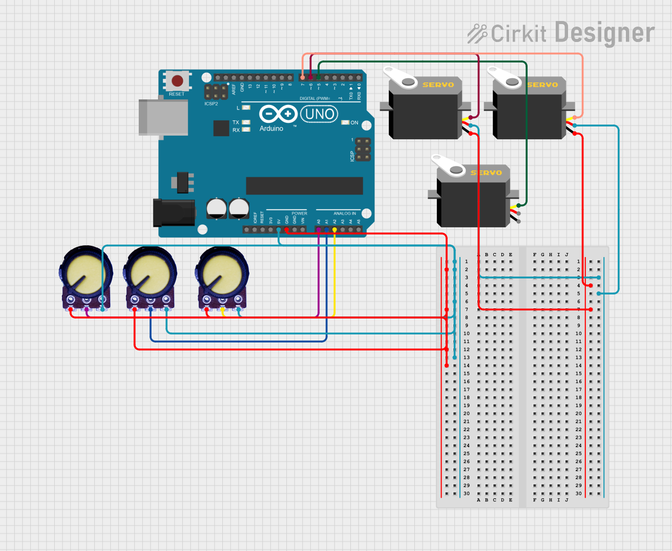
Circuit Documentation
Summary of the Circuit
This circuit is designed around an Arduino UNO microcontroller, which interfaces with multiple potentiometers and servo motors. The potentiometers are used as analog input devices, likely for controlling the position or speed of the servo motors. The servo motors are controlled by the Arduino UNO through digital output pins. The circuit is powered by the Arduino UNO's 5V output, which also supplies power to the potentiometers and servo motors.
Component List
Arduino UNO
- Description: A microcontroller board based on the ATmega328P.
- Purpose: Acts as the central processing unit of the circuit, reading inputs from potentiometers and controlling the servo motors.
Servo Motor
- Description: An actuator that enables precise control of angular position.
- Purpose: To perform mechanical actions as instructed by the Arduino UNO.
Potentiometer
- Description: A three-terminal resistor with a rotating contact that forms an adjustable voltage divider.
- Purpose: To provide a variable analog input to the Arduino UNO for controlling the servo motors.
Wiring Details
Arduino UNO
- 5V: Connected to the VCC pins of all potentiometers.
- GND: Connected to the GND pins of all potentiometers and servo motors.
- A0: Connected to the Output pin of one potentiometer.
- A1: Connected to the Output pin of another potentiometer.
- A2: Connected to the Output pin of the third potentiometer.
- D5: Connected to the pulse pin of one servo motor.
- D6: Connected to the pulse pin of another servo motor.
- D7: Connected to the pulse pin of the third servo motor.
Servo Motors
- VCC: Connected to the 5V supply from the Arduino UNO.
- GND: Connected to the ground (GND) on the Arduino UNO.
- Pulse: Connected to digital pins D5, D6, or D7 on the Arduino UNO for control signals.
Potentiometers
- VCC: Connected to the 5V supply from the Arduino UNO.
- GND: Connected to the ground (GND) on the Arduino UNO.
- Output: Connected to analog input pins A0, A1, or A2 on the Arduino UNO.
Documented Code
void setup() {
  // put your setup code here, to run once:

}

void loop() {
  // put your main code here, to run repeatedly:

}
File: sketch.ino
The provided code is a template with empty setup() and loop() functions. The setup() function is intended for initialization code that runs once when the program starts, such as configuring pin modes. The loop() function contains the main logic of the program, which runs continuously after the setup() function completes. Specific code to read the potentiometer values and control the servo motors should be added to these functions.