
Solar-Powered Wi-Fi Controlled Light with ESP8266 and TP4056
View and Edit Project In Cirkit Designer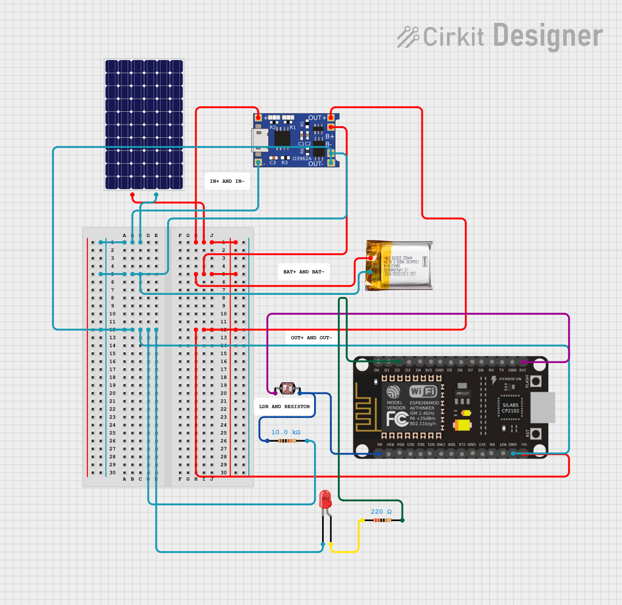
Circuit Documentation
Summary
This circuit is designed to utilize a solar panel to charge a 3.7V LiPo battery through a TP4056 charging module. The circuit also includes an ESP8266 NodeMCU microcontroller, a photocell (LDR) for light detection, a red LED for visual indication, and resistors for current limiting and voltage division.
Component List
Solar Panel
- Description: Converts sunlight into electrical energy.
- Pins: +, -
TP4056
- Description: Lithium-ion battery charger module.
- Pins: IN-, IN+, B-, B+, OUT-, OUT+
3.7V LiPo Battery
- Description: Rechargeable lithium polymer battery.
- Pins: +Ve, GND
ESP8266 NodeMCU
- Description: Wi-Fi enabled microcontroller.
- Pins: D0, D1, D2, D3, D4, 3V3, GND, D5, D6, D7, D8, RX, TX, A0, RSV, SD3, SD2, SD1, CMD, SD0, CLK, EN, RST, VIN
Photocell (LDR)
- Description: Light-dependent resistor for detecting light levels.
- Pins: pin 0, pin 1
Resistor (10k Ohms)
- Description: Limits current and divides voltage.
- Pins: pin1, pin2
- Properties: Resistance: 10k Ohms
Resistor (220 Ohms)
- Description: Limits current.
- Pins: pin1, pin2
- Properties: Resistance: 220 Ohms
LED: Two Pin (Red)
- Description: Light-emitting diode for visual indication.
- Pins: anode, cathode
Wiring Details
Solar Panel
+ connected to:
- TP4056 (IN+)
- TP4056 (B+)
- 3.7V LiPo Battery (+Ve)
- ESP8266 NodeMCU (VIN)
- TP4056 (OUT+)
- connected to:
- TP4056 (IN-)
- TP4056 (B-)
- 3.7V LiPo Battery (GND)
- Resistor (10k Ohms) (pin2)
- LED (cathode)
- ESP8266 NodeMCU (GND)
- TP4056 (OUT-)
TP4056
IN- connected to:
- Solar Panel (-)
- TP4056 (B-)
- 3.7V LiPo Battery (GND)
- Resistor (10k Ohms) (pin2)
- LED (cathode)
- ESP8266 NodeMCU (GND)
- TP4056 (OUT-)
IN+ connected to:
- Solar Panel (+)
- TP4056 (B+)
- 3.7V LiPo Battery (+Ve)
- ESP8266 NodeMCU (VIN)
- TP4056 (OUT+)
B- connected to:
- Solar Panel (-)
- TP4056 (IN-)
- 3.7V LiPo Battery (GND)
- Resistor (10k Ohms) (pin2)
- LED (cathode)
- ESP8266 NodeMCU (GND)
- TP4056 (OUT-)
B+ connected to:
- Solar Panel (+)
- TP4056 (IN+)
- 3.7V LiPo Battery (+Ve)
- ESP8266 NodeMCU (VIN)
- TP4056 (OUT+)
OUT- connected to:
- Solar Panel (-)
- TP4056 (IN-)
- TP4056 (B-)
- 3.7V LiPo Battery (GND)
- Resistor (10k Ohms) (pin2)
- LED (cathode)
- ESP8266 NodeMCU (GND)
OUT+ connected to:
- Solar Panel (+)
- TP4056 (IN+)
- TP4056 (B+)
- 3.7V LiPo Battery (+Ve)
- ESP8266 NodeMCU (VIN)
3.7V LiPo Battery
+Ve connected to:
- Solar Panel (+)
- TP4056 (IN+)
- TP4056 (B+)
- ESP8266 NodeMCU (VIN)
- TP4056 (OUT+)
GND connected to:
- Solar Panel (-)
- TP4056 (IN-)
- TP4056 (B-)
- Resistor (10k Ohms) (pin2)
- LED (cathode)
- ESP8266 NodeMCU (GND)
- TP4056 (OUT-)
ESP8266 NodeMCU
GND connected to:
- Solar Panel (-)
- TP4056 (IN-)
- TP4056 (B-)
- 3.7V LiPo Battery (GND)
- Resistor (10k Ohms) (pin2)
- LED (cathode)
- TP4056 (OUT-)
VIN connected to:
- Solar Panel (+)
- TP4056 (IN+)
- TP4056 (B+)
- 3.7V LiPo Battery (+Ve)
- TP4056 (OUT+)
D2 connected to:
- Resistor (220 Ohms) (pin2)
3V3 connected to:
- Photocell (LDR) (pin 0)
A0 connected to:
- Resistor (10k Ohms) (pin1)
- Photocell (LDR) (pin 1)
Photocell (LDR)
pin 0 connected to:
- ESP8266 NodeMCU (3V3)
pin 1 connected to:
- Resistor (10k Ohms) (pin1)
- ESP8266 NodeMCU (A0)
Resistor (10k Ohms)
pin1 connected to:
- ESP8266 NodeMCU (A0)
- Photocell (LDR) (pin 1)
pin2 connected to:
- Solar Panel (-)
- TP4056 (IN-)
- TP4056 (B-)
- 3.7V LiPo Battery (GND)
- LED (cathode)
- ESP8266 NodeMCU (GND)
- TP4056 (OUT-)
Resistor (220 Ohms)
pin1 connected to:
- LED (anode)
pin2 connected to:
- ESP8266 NodeMCU (D2)
LED: Two Pin (Red)
anode connected to:
- Resistor (220 Ohms) (pin1)
cathode connected to:
- Solar Panel (-)
- TP4056 (IN-)
- TP4056 (B-)
- 3.7V LiPo Battery (GND)
- Resistor (10k Ohms) (pin2)
- ESP8266 NodeMCU (GND)
- TP4056 (OUT-)
Code
No code is provided for this circuit.