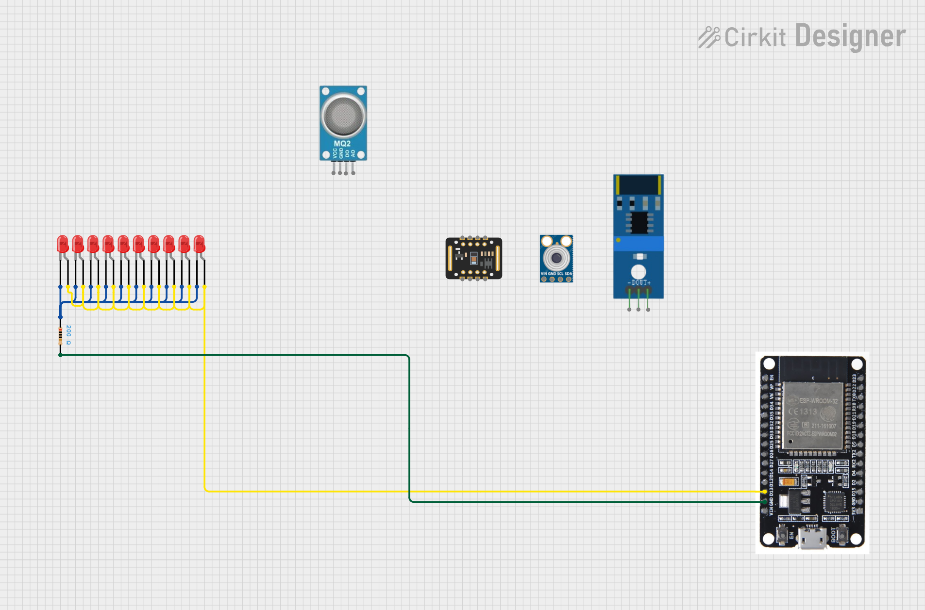
ESP32-Controlled Multi-LED Indicator System

Circuit Documentation
Summary of the Circuit
This circuit primarily consists of an ESP32 microcontroller unit (MCU) interfaced with multiple red LEDs and a single resistor. The ESP32 is responsible for controlling the LEDs, which are likely used as indicators or for display purposes. The LEDs are connected in parallel to a digital pin (D13) on the ESP32 through a current-limiting resistor. The ground pins of the LEDs are connected together and then to the ground (GND) of the ESP32, completing the circuit.
Component List
ESP32
- Description: A powerful microcontroller with Wi-Fi and Bluetooth capabilities, suitable for a wide range of applications.
- Pins: EN, VP, VN, D34, D35, D32, D33, D25, D26, D27, D14, D12, D13, GND, VIN, 3V3, D15, D2, D4, RX2, TX2, D5, D18, D19, D21, RX0, TX0, D22, D23, BOOT
MAX30102
- Description: An integrated pulse oximetry and heart-rate monitor sensor solution.
- Pins: VIN, SDA, SCL, GND, RD, IRD, INT
mlx90614
- Description: An infrared thermometer for non-contact temperature measurements.
- Pins: SDA, SCL, GND, VIN
801s shock sensor
- Description: A vibration sensor capable of detecting shocks and vibrations.
LED: Two Pin (red)
- Description: A standard red LED for indication purposes.
- Pins: cathode, anode
Resistor
- Description: A passive electrical component that provides resistance in the circuit.
- Value: 200 Ohms
mq2
- Description: A gas sensor used for detecting a variety of gases including LPG, smoke, and alcohol.
Wiring Details
ESP32
- D13: Connected to the anodes of all red LEDs.
- GND: Connected to one end of the resistor (pin2).
MAX30102
- Not connected in the current net list.
mlx90614
- Not connected in the current net list.
801s shock sensor
- Not connected in the current net list.
mq2
- Not connected in the current net list.
LEDs: Two Pin (red)
- Anode: Connected to ESP32 D13.
- Cathode: Connected to one end of the resistor (pin1).
Resistor
- Pin1: Connected to the cathodes of all red LEDs.
- Pin2: Connected to ESP32 GND.
Documented Code
No code has been provided for the microcontrollers in the circuit. The ESP32 would typically be programmed to control the state of the LEDs, but without the code, we cannot document the behavior or functionality implemented for the ESP32.
Please note that the documentation assumes that the provided net list is complete and that no other connections exist. If there are additional components or connections not listed, they should be included in the documentation accordingly.