
Circuit Documentation
Summary of the Circuit
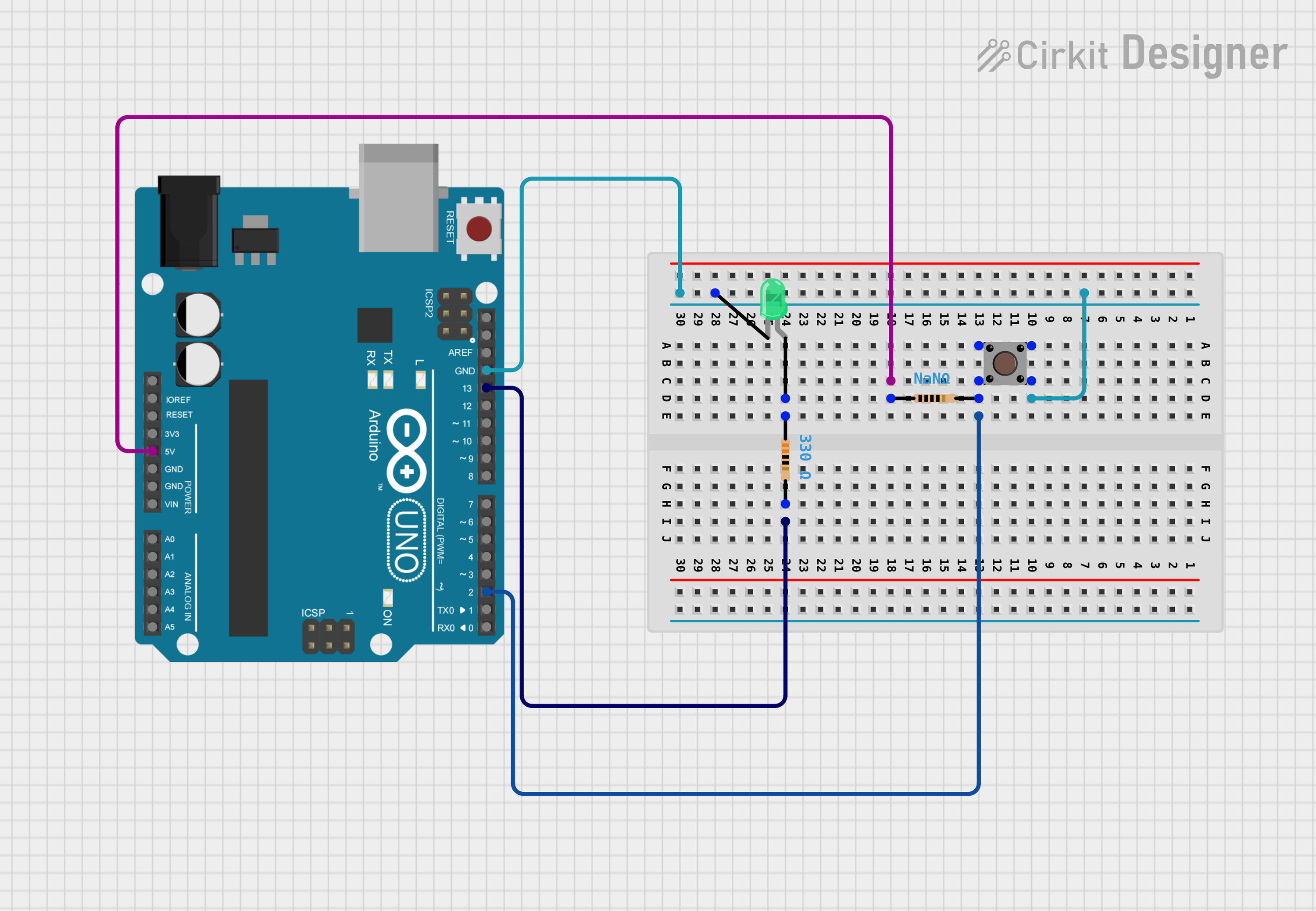
This circuit is designed to control a green LED using an Arduino UNO microcontroller and a pushbutton. The LED is turned on when the pushbutton is pressed. The pushbutton is configured with an internal pull-up resistor and is connected to ground when pressed. The circuit includes two resistors, one of which is used to limit the current through the LED, and the other's value is not specified (NaN).
Component List
Arduino UNO
- Description: A microcontroller board based on the ATmega328P.
- Purpose: Acts as the central controller for the circuit, reading the pushbutton state and controlling the LED.
Resistor (330 Ohms)
- Description: A passive two-terminal electrical component that implements electrical resistance as a circuit element.
- Purpose: Limits the current flowing through the LED to prevent damage.
Resistor (Unspecified Value)
- Description: A passive two-terminal electrical component that implements electrical resistance as a circuit element.
- Purpose: The purpose is not specified due to the missing resistance value.
LED: Two Pin (green)
- Description: A two-pin light-emitting diode that emits green light.
- Purpose: Serves as a visual indicator that is controlled by the Arduino UNO.
Pushbutton
- Description: A simple switch mechanism for controlling some aspect of a machine or a process.
- Purpose: Provides a user interface to control the LED.
Wiring Details
Arduino UNO
- 5V: Connected to one pin of an unspecified resistor.
- GND: Connected to the cathode of the LED and one side of the pushbutton.
- D2: Connected to one side of the pushbutton.
- D13: Connected to one pin of the 330 Ohm resistor.
Resistor (330 Ohms)
- pin1: Connected to the anode of the LED.
- pin2: Connected to pin D13 of the Arduino UNO.
Resistor (Unspecified Value)
- pin1: Connected to the 5V pin of the Arduino UNO.
- pin2: The purpose and connection are not specified due to the missing resistance value.
LED: Two Pin (green)
- anode: Connected to pin1 of the 330 Ohm resistor.
- cathode: Connected to the GND pin of the Arduino UNO.
Pushbutton
- Pin 1 (in) and Pin 3 (out): Connected to each other and to the cathode of the LED and GND pin of the Arduino UNO.
- Pin 2 (in) and Pin 4 (out): Connected to each other and to pin D2 of the Arduino UNO.
Documented Code
/*
 * This Arduino sketch controls a green LED with a button.
 * The button uses the internal pull-up resistor and is connected to ground
 * when pressed. When the button is pressed, the LED will turn on.
 */

const int buttonPin = 2; // Pin connected to the button
const int ledPin = 13;   // Pin connected to the green LED

void setup() {
  // Initialize the button pin as an input with internal pull-up resistor
  pinMode(buttonPin, INPUT_PULLUP);
  // Initialize the LED pin as an output
  pinMode(ledPin, OUTPUT);
}

void loop() {
  // Read the state of the button
  int buttonState = digitalRead(buttonPin);
  // If the button is pressed, turn on the LED
  if (buttonState == LOW) {
    digitalWrite(ledPin, HIGH);
  } else {
    // Otherwise, turn off the LED
    digitalWrite(ledPin, LOW);
  }
}
The code is written for the Arduino UNO microcontroller. It sets up the button and LED pins, reads the button state, and controls the LED accordingly. The button is configured with an internal pull-up resistor, and the LED is turned on when the button is pressed (when the button state is LOW).