
ESP32-Controlled Dual Ultrasonic Sensor and Line Tracking Robot
View and Edit Project In Cirkit Designer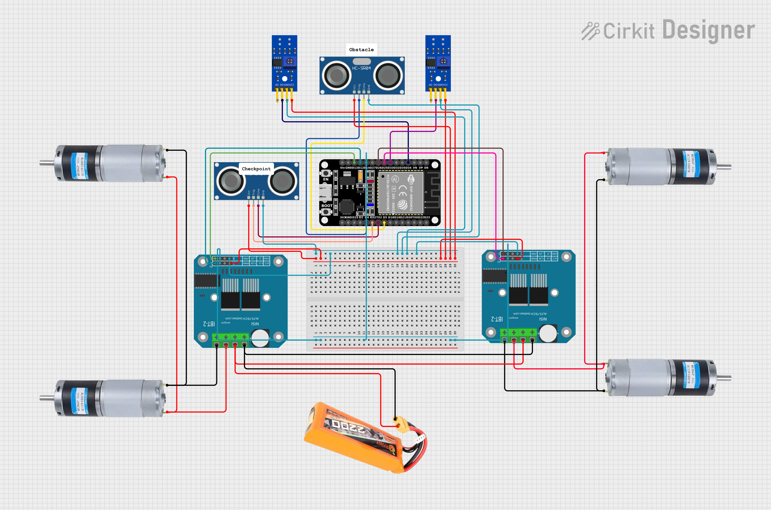
Circuit Documentation
Summary
The circuit in question is designed to interface an ESP32 microcontroller with various sensors and motor drivers. It includes two HC-SR04 ultrasonic sensors for distance measurement, two KY-033 line tracking sensors for detecting lines or edges, two BTS7960 motor drivers for controlling high-power motors, and four DC motors. The circuit is powered by a LiPo battery with a capacity of 2200mAh and a discharge rate of 30C.
Component List
Microcontrollers
- ESP32 (30 pin): A microcontroller with Wi-Fi and Bluetooth capabilities, featuring a wide range of GPIO pins for interfacing with sensors and actuators.
Sensors
- HC-SR04 Ultrasonic Sensor: A sensor used for measuring distances via ultrasonic waves.
- KY-033 Line Tracking Sensor: A sensor used for detecting lines or edges based on light reflectivity.
Motor Drivers
- BTS7960 Motor Driver: A high-power motor driver capable of driving large DC motors with high current.
Motors
- DC Motor: A simple electric motor that runs on direct current (DC) electricity.
Power Supply
- LiPo Battery 2200mAh 30C: A rechargeable battery that provides power to the circuit.
Wiring Details
HC-SR04 Ultrasonic Sensor
- VCC: Connected to a power distribution net that includes the VCC pins of other sensors and motor drivers.
- GND: Connected to a ground distribution net that includes the GND pins of other sensors and motor drivers.
- TRIG: Connected to the ESP32 for triggering ultrasonic pulses.
- ECHO: Connected to the ESP32 for receiving the echo pulses.
KY-033 Line Tracking Sensor
- VCC: Connected to the same power distribution net as the HC-SR04's VCC.
- GND: Connected to the same ground distribution net as the HC-SR04's GND.
- D0: Connected to the ESP32 for digital signal output.
BTS7960 Motor Driver
- Pin 3, Pin 7: Connected to the ESP32 for control signals.
- Pin 5: Connected to the power distribution net.
- Pin 1: Connected to the ground distribution net.
- Pin 8, Pin 4: Connected to the ESP32 for PWM control signals.
- Pin 9, Pin 10: Connected to the DC motors for driving the motors.
- Pin 11, Pin 12: Connected to the LiPo battery for power supply.
DC Motor
- Positive: Connected to the BTS7960 motor driver.
- Negative: Connected to the BTS7960 motor driver.
LiPo Battery 2200mAh 30C
- VCC: Provides power to the BTS7960 motor drivers.
- GND: Provides a common ground for the circuit.
Documented Code
No code has been provided for the microcontrollers in the circuit. The ESP32 would typically be programmed to control the sensors and motor drivers based on the application requirements. The code would include initialization of the GPIO pins, setup of the PWM channels for motor control, and algorithms for processing sensor data to make decisions about motor control.