
Arduino UNO Based Solar-Powered Data Logger with RTC and SD Card Storage
View and Edit Project In Cirkit Designer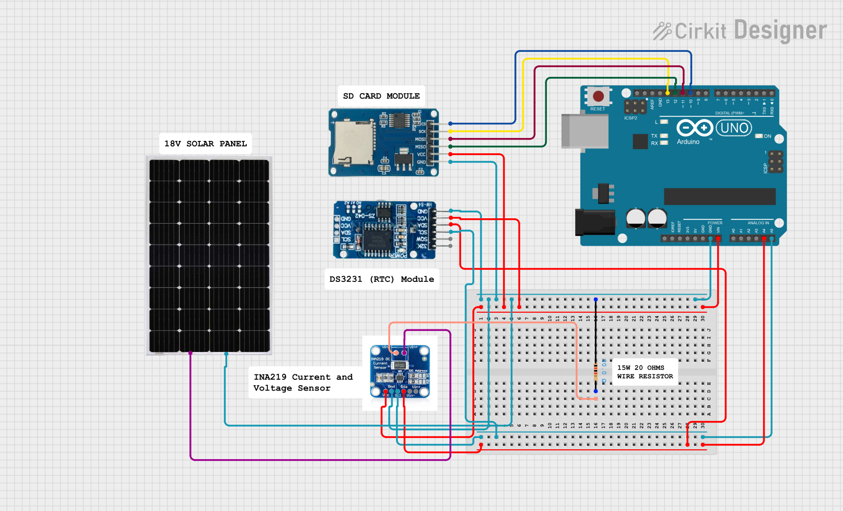
Circuit Documentation
Summary
This circuit integrates an Arduino UNO with a Micro SD Card Module, a Real-Time Clock (RTC DS3231), an INA219 current sensor, and a Solar Panel. The Arduino UNO serves as the central microcontroller, interfacing with the SD card module for data storage, the RTC for timekeeping, and the INA219 for monitoring voltage and current from the Solar Panel. A resistor is included for protection or voltage division purposes.
Component List
Arduino UNO
- Microcontroller board based on the ATmega328P
- It has 14 digital input/output pins, 6 analog inputs, a 16 MHz quartz crystal, a USB connection, a power jack, an ICSP header, and a reset button.
Micro SD Card Module
- A module that allows micro SD cards to be read and written to via SPI.
RTC DS3231
- A highly accurate I2C real-time clock (RTC) with an integrated temperature-compensated crystal oscillator (TCXO) and crystal.
Solar Panel
- A photovoltaic panel designed to absorb the sun's rays as a source of energy for generating electricity.
INA219
- A high-side current shunt and power monitor with an I2C interface.
Resistor
- A passive two-terminal electrical component that implements electrical resistance as a circuit element. This particular resistor has a resistance of 20 Ohms.
Wiring Details
Arduino UNO
A4 (SDA)connected to the SDA line shared with INA219 and RTC DS3231 for I2C communication.A5 (SCL)connected to the SCL line shared with INA219 and RTC DS3231 for I2C communication.Vinconnected to the VCC lines of INA219, Micro SD Card Module, and RTC DS3231.GNDconnected to the common ground network.D13connected to thesckpin of the Micro SD Card Module for SPI communication.D12connected to themisopin of the Micro SD Card Module for SPI communication.D11connected to themosipin of the Micro SD Card Module for SPI communication.D10connected to thecspin of the Micro SD Card Module for SPI communication.
Micro SD Card Module
vccconnected to the VCC network.gndconnected to the common ground network.csconnected toD10on the Arduino UNO.sckconnected toD13on the Arduino UNO.mosiconnected toD11on the Arduino UNO.misoconnected toD12on the Arduino UNO.
RTC DS3231
VCCconnected to the VCC network.GNDconnected to the common ground network.SCLconnected toA5 (SCL)on the Arduino UNO.SDAconnected toA4 (SDA)on the Arduino UNO.
Solar Panel
+connected toVin+on the INA219.-connected to the common ground network.
INA219
Vin+connected to the+of the Solar Panel.Vin-connected topin2of the Resistor.VCCconnected to the VCC network.GNDconnected to the common ground network.Sclconnected toA5 (SCL)on the Arduino UNO.Sdaconnected toA4 (SDA)on the Arduino UNO.
Resistor
pin1connected to the common ground network.pin2connected toVin-on the INA219.
Documented Code
Arduino UNO Code (sketch.ino)
void setup() {
  // put your setup code here, to run once:

}

void loop() {
  // put your main code here, to run repeatedly:

}
Additional Notes (documentation.txt)
No additional code documentation was provided for the Arduino UNO.