Solar-Powered Smart Home Control System with ATS and IoT Integration
Circuit Documentation
Summary
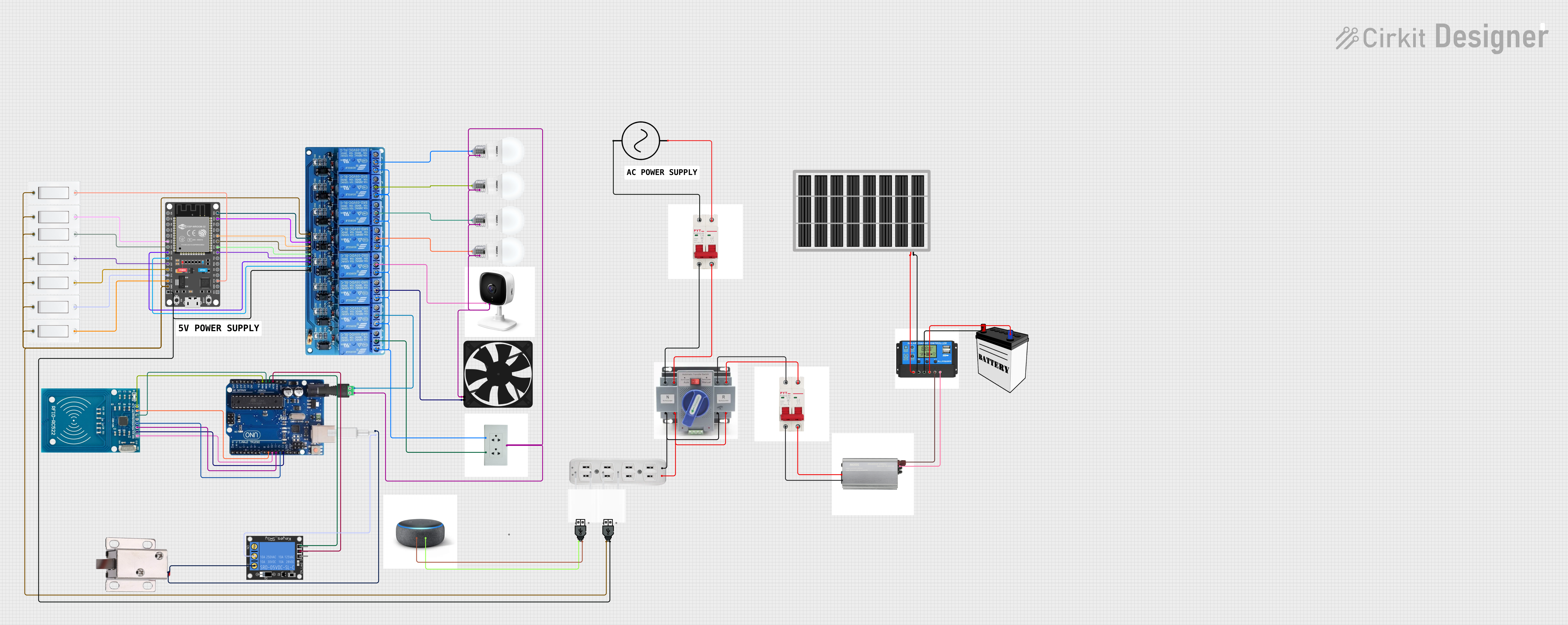
The circuit described in the provided data is a complex system that includes power sources (a 12V battery and a solar panel), power management (a charge controller, ATS, and inverters), protection devices (circuit breakers), control elements (ESP 32 microcontroller and relays), user interfaces (flush switches), output devices (bulbs, CCTV, fan, solenoid lock), and communication modules (RFID-RC522, Alexa). The circuit appears to be designed for a smart home or security system with automated control over lighting, power supply, and security features.
Component List
Power Sources
- 12V Battery: Provides the main DC power supply.
- Solar Panel: An alternative renewable energy source.
Power Management
- ATS (Automatic Transfer Switch): Manages power input sources.
- Inverter (500 watts): Converts DC power from the battery to AC power.
- Charge Controller: Regulates the charging of the battery from the solar panel and controls power distribution.
Protection Devices
- Circuit Breakers (10ahm): Provide overcurrent protection.
Control Elements
- ESP 32 DEVKIT V1 (30 pins): A microcontroller for managing the logic and control functions of the circuit.
- 5V 8-Channel Relay: Allows the ESP 32 to control higher power devices.
User Interfaces
- Flush Switches: Manual input devices for user control.
Output Devices
- Bulbs: Lighting elements.
- CCTV: Security camera.
- Fan: Air circulation device.
- 12V Solenoid Lock: Electromechanical locking mechanism.
Communication Modules
- RFID-RC522: A module for RFID communication.
- Arduino Uno R3: A microcontroller that could be used for managing the RFID module.
- Alexa: Voice-controlled smart assistant for user interaction.
Miscellaneous
- AC Supply: Provides AC power to the circuit.
- 5V Adapter: Converts AC to a 5V DC supply.
- USB Power: Provides 5V power from a USB source.
Wiring Details
Power Sources
12V Battery
VCCconnected to Charge Controller Battery Positive.GNDconnected to Charge Controller Battery Negative.
Solar Panel
vccconnected to Charge Controller Solar Positive.gndconnected to Charge Controller Solar Negative.
Power Management
ATS
+connected to circuit breakers and AC SUPPLY +ve.-connected to circuit breakers and AC SUPPLY -ve.
Inverter (500 watts)
positiveconnected to Charge Controller Load Positive.negativeconnected to Charge Controller Load Negative.1and2connected to circuit breaker.
Charge Controller
Battery PositiveandBattery Negativeconnected to 12V Battery.Load PositiveandLoad Negativeconnected to inverter.Solar PositiveandSolar Negativeconnected to Solar Panel.
Protection Devices
- Circuit Breakers (10ahm)
+and-connected to ATS and various components like AC SUPPLY, inverter, and outlets.
Control Elements
ESP 32 DEVKIT V1 (30 pins)
GNDconnected to the ground of various components.VINconnected to 5V 8-Channel Relay VCC and USB power +.- Digital pins
D23,D22,D21,D19,D18,D5,D25,D26,D27,D33,D32,D13,D12,D14,D15connected to corresponding IN pins on the 5V 8-Channel Relay.
5V 8-Channel Relay
GNDconnected to ESP 32 GND.VCCconnected to ESP 32 VIN and USB power +.IN1toIN8connected to corresponding ESP 32 digital pins.C(Common) pins connected to various output devices.NO(Normally Open) pins connected to socket.
User Interfaces
- Flush Switches
GNDconnected to ESP 32 GND.VCCconnected to corresponding ESP 32 digital pins.
Output Devices
Bulbs
+connected to 5V 8-Channel Relay C pins.-connected to socket.
CCTV
1connected to 5V 8-Channel Relay C pin.2connected to socket.
Fan
5Vconnected to socket.GNDconnected to 5V 8-Channel Relay C pin.
12V Solenoid Lock
GNDconnected to 1-Channel Relay NC and W.VCCnot specified in the net list.
Communication Modules
RFID-RC522
VCC (3.3V)connected to Arduino Uno 3.3V.GND,SCK,MISO,MOSI,SDA,RSTconnected to corresponding Arduino Uno pins.
Arduino Uno R3
3.3Vand5Vconnected to RFID-RC522 and 1-Channel Relay power.GNDconnected to RFID-RC522 and 1-Channel Relay ground.- Digital pins
13,12,11,10,9connected to corresponding RFID-RC522 pins.
Alexa
1and2connected to USB power + and -.
Documented Code
No code was provided in the input data. Therefore, this section is not applicable for the current documentation. If code becomes available, it should be documented here with appropriate descriptions of its functionality and how it interacts with the hardware components.