
Arduino Nano-Based Health Monitoring Device with Wireless Data Transmission
View and Edit Project In Cirkit Designer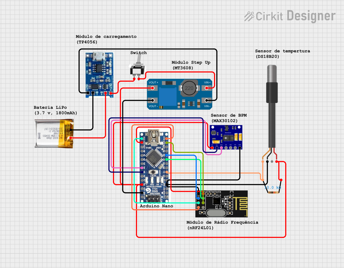
Circuit Documentation
Summary
This circuit integrates various components to create a system capable of temperature sensing, heart rate and oxygen level monitoring, and wireless communication. The core of the circuit is an Arduino Nano, which interfaces with a DS18B20 temperature sensor, a MAX30102 heart rate and oxygen sensor, and an NRF24L01 wireless communication module. A resistor is used for pull-up configuration in the temperature sensor setup. Power management is handled by a lipo battery charger module, a 3.7v LiPo battery, and an MT3608 boost converter. A toggle switch is included to control the power flow.
Component List
- Arduino Nano: A compact microcontroller board based on the ATmega328P, featuring digital and analog I/O pins.
- DS18B20 1-Wire Temperature Sensor Probe Cable: A digital temperature sensor that communicates over a 1-Wire bus.
- MAX30102 Heart Rate and Oxygen Sensor: An integrated pulse oximetry and heart-rate monitor sensor module.
- Resistor (10k Ohms): A passive two-terminal electrical component used to limit current flow.
- Lipo Battery Charger Module: A module used for charging lithium polymer batteries.
- 3.7v LiPo Battery: A rechargeable battery that provides power to the circuit.
- MT3608: A DC-DC step-up converter module that boosts the voltage.
- Toggle Switch (SPST): A single-pole single-throw switch used to control the power supply.
- NRF24L01: A wireless transceiver module that operates in the 2.4 GHz band.
Wiring Details
Arduino Nano
- D12 connected to NRF24L01 MISO
- D11 connected to NRF24L01 MOSI
- D8 connected to NRF24L01 CE
- D7 connected to NRF24L01 CSN
- D4 connected to DS18B20 shield (via 10k Ohm resistor)
- D13 connected to NRF24L01 SCK
- 3V3 connected to NRF24L01 VCC (3V)
- A4 connected to MAX30102 SDA
- A5 connected to MAX30102 SCL
- 5V connected to MT3608 VOUT+ (also connected to MAX30102 VIN, DS18B20 VDD)
- GND connected to common ground net (shared with MAX30102 GND, DS18B20 GND, NRF24L01 GND, MT3608 VOUT-)
DS18B20 1-Wire Temperature Sensor Probe Cable
- Shield connected to Arduino Nano D4 (via 10k Ohm resistor)
- GND connected to common ground net
- VDD connected to MT3608 VOUT+
MAX30102 Heart Rate and Oxygen Sensor
- VIN connected to MT3608 VOUT+
- SCL connected to Arduino Nano A5
- SDA connected to Arduino Nano A4
- GND connected to common ground net
Resistor (10k Ohms)
- Pin1 connected to DS18B20 shield
- Pin2 connected to MT3608 VOUT+
Lipo Battery Charger Module
- B- connected to 3.7v LiPo GND
- B+ connected to 3.7v LiPo +Ve
- OUT- connected to MT3608 VIN-
- OUT+ connected to Toggle Switch L1
3.7v LiPo Battery
- GND connected to Lipo Battery Charger Module B-
- +Ve connected to Lipo Battery Charger Module B+
MT3608
- VOUT+ connected to Arduino Nano 5V, MAX30102 VIN, DS18B20 VDD
- VOUT- connected to common ground net
- VIN- connected to Lipo Battery Charger Module OUT-
- VIN+ connected to Toggle Switch COM
Toggle Switch (SPST)
- L1 connected to Lipo Battery Charger Module OUT+
- COM connected to MT3608 VIN+
NRF24L01
- MISO connected to Arduino Nano D12
- MOSI connected to Arduino Nano D11
- CE connected to Arduino Nano D8
- CSN connected to Arduino Nano D7
- SCK connected to Arduino Nano D13
- VCC (3V) connected to Arduino Nano 3V3
- GND connected to common ground net
Documented Code
Arduino Nano Code (sketch.ino)
void setup() {
  // put your setup code here, to run once:

}

void loop() {
  // put your main code here, to run repeatedly:

}
Note: The provided code is a template and does not include specific functionality. It should be populated with the setup and loop code required to initialize and control the connected sensors and wireless module.