
Circuit Documentation
Summary
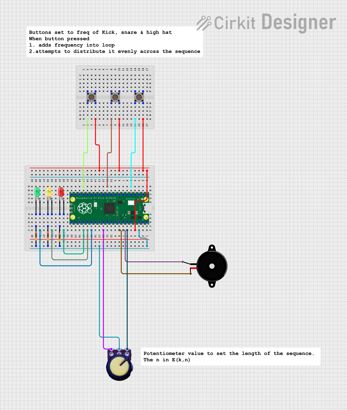
This circuit is built around the Raspberry Pi Pico microcontroller and includes various input and output components. The input components consist of three pushbuttons and a potentiometer, while the output components include a piezo speaker and three LEDs (red, green, and yellow). Each LED is connected in series with a 200 Ohm resistor to limit the current. The potentiometer is used to provide an adjustable voltage input to the Raspberry Pi Pico. The pushbuttons are used to trigger different inputs to the microcontroller. The piezo speaker is directly connected to the Raspberry Pi Pico for audio output.
Component List
- Raspberry Pi Pico: A microcontroller board based on the RP2040 microcontroller chip.
- Pushbutton: A momentary switch that closes the circuit when pressed.
- LED (Red, Green, Yellow): Light Emitting Diodes that emit red, green, and yellow light, respectively.
- Resistor (200 Ohms): A passive two-terminal electrical component that provides resistance to the flow of current.
- Piezo Speaker: An electronic device that can produce sound when an electrical signal is applied.
- Potentiometer: A three-terminal resistor with a rotating contact that forms an adjustable voltage divider.
Wiring Details
Raspberry Pi Pico
- GPIO 38: Connected to the junction of three 200 Ohm resistors and the output of the potentiometer.
- GPIO 37: Connected to the input pins of all three pushbuttons.
- GPIO 5: Connected to the output of the third pushbutton.
- GPIO 35: Connected to the ground terminal of the potentiometer.
- GPIO 34: Connected to one terminal of the piezo speaker.
- GPIO 33: Connected to the other terminal of the piezo speaker.
- GPIO 11: Connected to the output of the second pushbutton.
- GPIO 29: Connected to the VCC terminal of the potentiometer.
- GPIO 26: Connected to the anode of the green LED.
- GPIO 25: Connected to the anode of the yellow LED.
- GPIO 17: Connected to the output of the first pushbutton.
- GPIO 24: Connected to the anode of the red LED.
Pushbuttons
- All pushbuttons have one input pin connected to GPIO 37 of the Raspberry Pi Pico.
- The output of the first pushbutton is connected to GPIO 17.
- The output of the second pushbutton is connected to GPIO 11.
- The output of the third pushbutton is connected to GPIO 5.
LEDs
- The anode of the red LED is connected to GPIO 24, and its cathode is connected to one terminal of a 200 Ohm resistor.
- The anode of the green LED is connected to GPIO 26, and its cathode is connected to one terminal of a 200 Ohm resistor.
- The anode of the yellow LED is connected to GPIO 25, and its cathode is connected to one terminal of a 200 Ohm resistor.
Resistors
- All resistors are 200 Ohms.
- Each resistor is connected in series with an LED and the other terminal of each resistor is connected to GPIO 38 of the Raspberry Pi Pico.
Piezo Speaker
- One terminal is connected to GPIO 34 and the other terminal is connected to GPIO 33 of the Raspberry Pi Pico.
Potentiometer
- The VCC terminal is connected to GPIO 29, the output terminal is connected to GPIO 38, and the GND terminal is connected to GPIO 35 of the Raspberry Pi Pico.
Documented Code
sketch.ino
void setup() {
  // put your setup code here, to run once:

}

void loop() {
  // put your main code here, to run repeatedly:

}
documentation.txt
(No additional documentation provided within the code file)