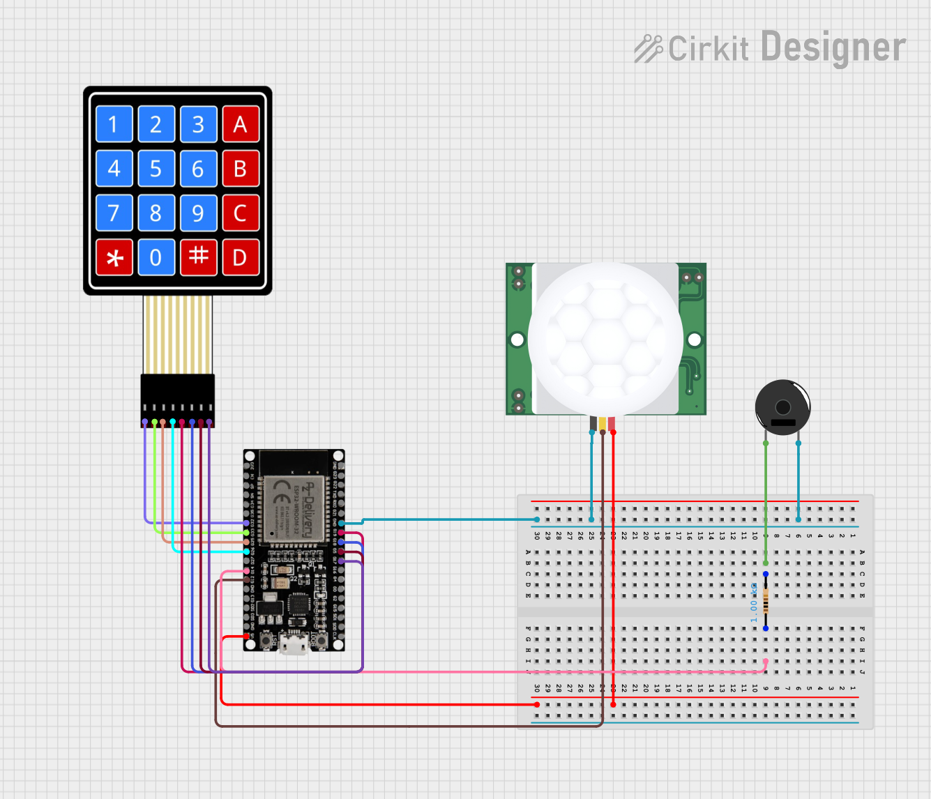
ESP32-Based Security System with PIR Motion Detection and Keypad Interface

Circuit Documentation
Summary
The circuit in question is designed to interface a 4x4 membrane matrix keypad with an ESP32 microcontroller, utilize a PIR (Passive Infrared) sensor for motion detection, and provide an audible alert through a piezo buzzer. The ESP32 microcontroller serves as the central processing unit, managing input from the keypad and the PIR sensor, and controlling the output to the piezo buzzer. A resistor is included in the circuit to limit the current to the piezo buzzer.
Component List
4X4 Membrane Matrix Keypad
- Description: A keypad with 16 buttons arranged in a 4x4 matrix.
- Pins: R1, R2, R3, R4, C1, C2, C3, C4
PIR HC-SR501
- Description: A motion sensor module that detects infrared signals from moving objects.
- Pins: VDD, SIG, GND
Piezo Buzzer
- Description: An electronic device that produces sound when an electrical signal is applied.
- Pins: pin 1, pin 2
Resistor
- Description: A passive two-terminal electrical component that implements electrical resistance as a circuit element.
- Pins: pin1, pin2
- Resistance: 1000 Ohms
ESP32 38 PINS
- Description: A microcontroller with Wi-Fi and Bluetooth capabilities and a wide range of GPIO pins.
- Pins: GND, G23, G22, TXD, RXD, G21, G19, G18, G5, G17, G16, G4, G0, G2, G15, SDI, SD0, CLK, 3V3, EN, SP, SN, G34, G35, G32, 33, G25, G26, G27, G14, G12, G13, SD2, SD3, 5V
Wiring Details
4X4 Membrane Matrix Keypad
- R1 connected to ESP32 pin G32
- R2 connected to ESP32 pin 33
- R3 connected to ESP32 pin G25
- R4 connected to ESP32 pin G26
- C1 connected to ESP32 pin G19
- C2 connected to ESP32 pin G18
- C3 connected to ESP32 pin G5
- C4 connected to ESP32 pin G17
PIR HC-SR501
- VDD connected to ESP32 pin 5V
- SIG connected to ESP32 pin G12
- GND connected to ESP32 pin GND
Piezo Buzzer
- pin 1 connected to one terminal of the Resistor
- pin 2 connected to ESP32 pin GND
Resistor
- pin1 connected to ESP32 pin G14
- pin2 connected to Piezo Buzzer pin 1
ESP32 38 PINS
- GND connected to Piezo Buzzer pin 2 and PIR HC-SR501 GND
- 5V connected to PIR HC-SR501 VDD
- G12 connected to PIR HC-SR501 SIG
- G14 connected to one terminal of the Resistor
- G32, 33, G25, G26, G19, G18, G5, G17 connected to the corresponding pins of the 4X4 Membrane Matrix Keypad
Documented Code
No code has been provided for the microcontroller. The documentation of the code would typically include a description of the functionality, setup, and loop routines, along with any functions or libraries used to interface with the components. Since no code is available, this section cannot be completed.