Arduino-Controlled Robotics Platform with L298N Motor Driver and Ultrasonic Sensing
Circuit Documentation
Summary
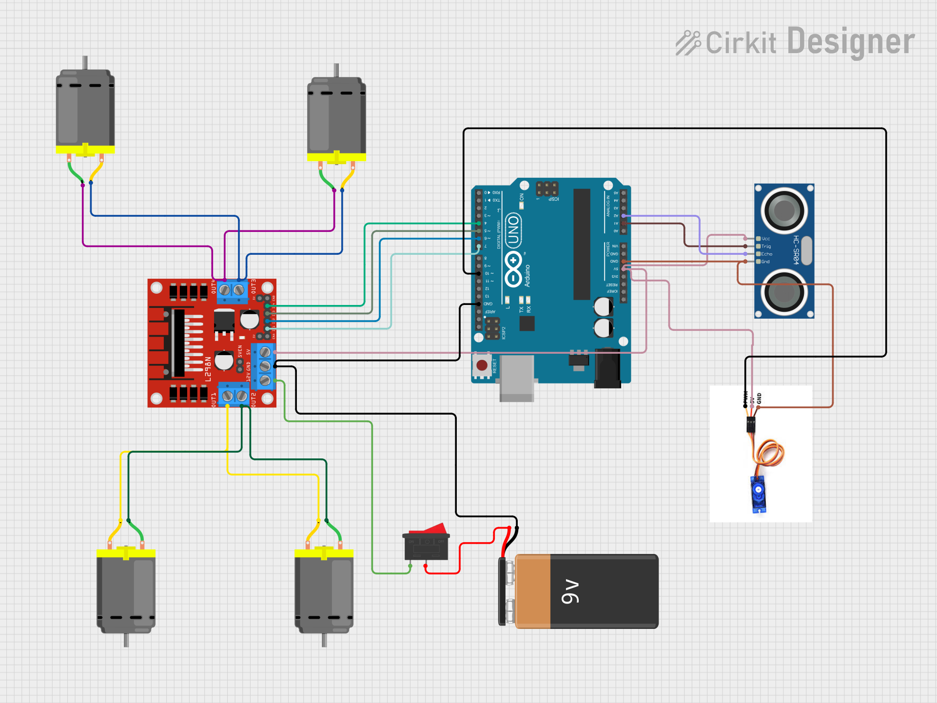
This circuit is designed to control multiple DC motors using an L298N DC motor driver, interfaced with an Arduino UNO microcontroller. The circuit also includes a 9V battery for power, an HC-SR04 ultrasonic sensor for distance measurement, an SG90 servo motor for angular positioning, and a rocker switch to control the power supply to the motor driver. The Arduino UNO is programmed to manage the inputs and outputs to control the motors, read sensor data, and drive the servo motor.
Component List
L298N DC Motor Driver
- Description: A motor driver module capable of driving two DC motors or one stepper motor.
- Pins: OUT1, OUT2, 12V, GND, 5V, OUT3, OUT4, ENA, IN1, IN2, IN3, IN4, ENB.
Arduino UNO
- Description: A microcontroller board based on the ATmega328P.
- Pins: IOREF, Reset, 3.3V, 5V, GND, Vin, A0-A5, SCL, SDA, AREF, D0-D13.
9V Battery
- Description: A standard 9V battery used to power the circuit.
- Pins: + (positive), - (negative).
DC Motor
- Description: A standard DC motor for rotational motion.
- Pins: pin 1, pin 2.
HC-SR04 Ultrasonic Sensor
- Description: An ultrasonic sensor used for measuring distances.
- Pins: VCC, TRIG, ECHO, GND.
SG90 Servo Motor
- Description: A small and lightweight servo motor for precise control of angular position.
- Pins: PWM, 5V, GND.
Rocker Switch
- Description: A switch to control the power supply to the motor driver.
- Pins: 1, 2.
Wiring Details
L298N DC Motor Driver
- OUT1, OUT2: Connected to one pair of DC motor terminals.
- OUT3, OUT4: Connected to another pair of DC motor terminals.
- 12V: Connected to one terminal of the rocker switch.
- GND: Common ground with Arduino UNO, HC-SR04, and SG90 servo motor.
- 5V: Connected to the 5V output of the Arduino UNO, also supplies power to the HC-SR04 and SG90 servo motor.
- ENA, ENB: Enable pins for the motor outputs (not detailed in the net list).
- IN1, IN2, IN3, IN4: Control inputs from the Arduino UNO digital pins D7, D6, D5, and D4 respectively.
Arduino UNO
- 5V: Provides power to the L298N motor driver, HC-SR04, and SG90 servo motor.
- GND: Common ground with L298N motor driver, HC-SR04, and SG90 servo motor.
- D4-D7: Control signals to the L298N motor driver.
- A1, A2: Connected to the TRIG and ECHO pins of the HC-SR04 ultrasonic sensor.
- D10: PWM output to control the SG90 servo motor.
9V Battery
- +: Connected to the second terminal of the rocker switch.
- -: Common ground with the circuit.
DC Motors
- pin 1, pin 2: Connected to the OUT1, OUT2, OUT3, and OUT4 of the L298N motor driver.
HC-SR04 Ultrasonic Sensor
- VCC: Powered by the 5V output from the L298N motor driver.
- TRIG: Connected to the A1 pin on the Arduino UNO.
- ECHO: Connected to the A2 pin on the Arduino UNO.
- GND: Common ground with the circuit.
SG90 Servo Motor
- PWM: Receives PWM signal from D10 on the Arduino UNO.
- 5V: Powered by the 5V output from the L298N motor driver.
- GND: Common ground with the circuit.
Rocker Switch
- Terminal 1: Connected to the 12V input on the L298N motor driver.
- Terminal 2: Connected to the + terminal of the 9V battery.
Documented Code
Arduino UNO Code (sketch.ino)
void setup() {
  // put your setup code here, to run once:

}

void loop() {
  // put your main code here, to run repeatedly:

}
The provided code is a template with empty setup and loop functions. The setup function is intended for initialization code that runs once when the Arduino is powered on or reset. The loop function contains code that runs continuously as long as the Arduino is powered. Specific functionality needs to be implemented within these functions to control the motors, read sensor data, and drive the servo motor based on the application requirements.