
Arduino Nano-Based Ultrasonic Sensor Array with Servo and DC Motor Control
View and Edit Project In Cirkit Designer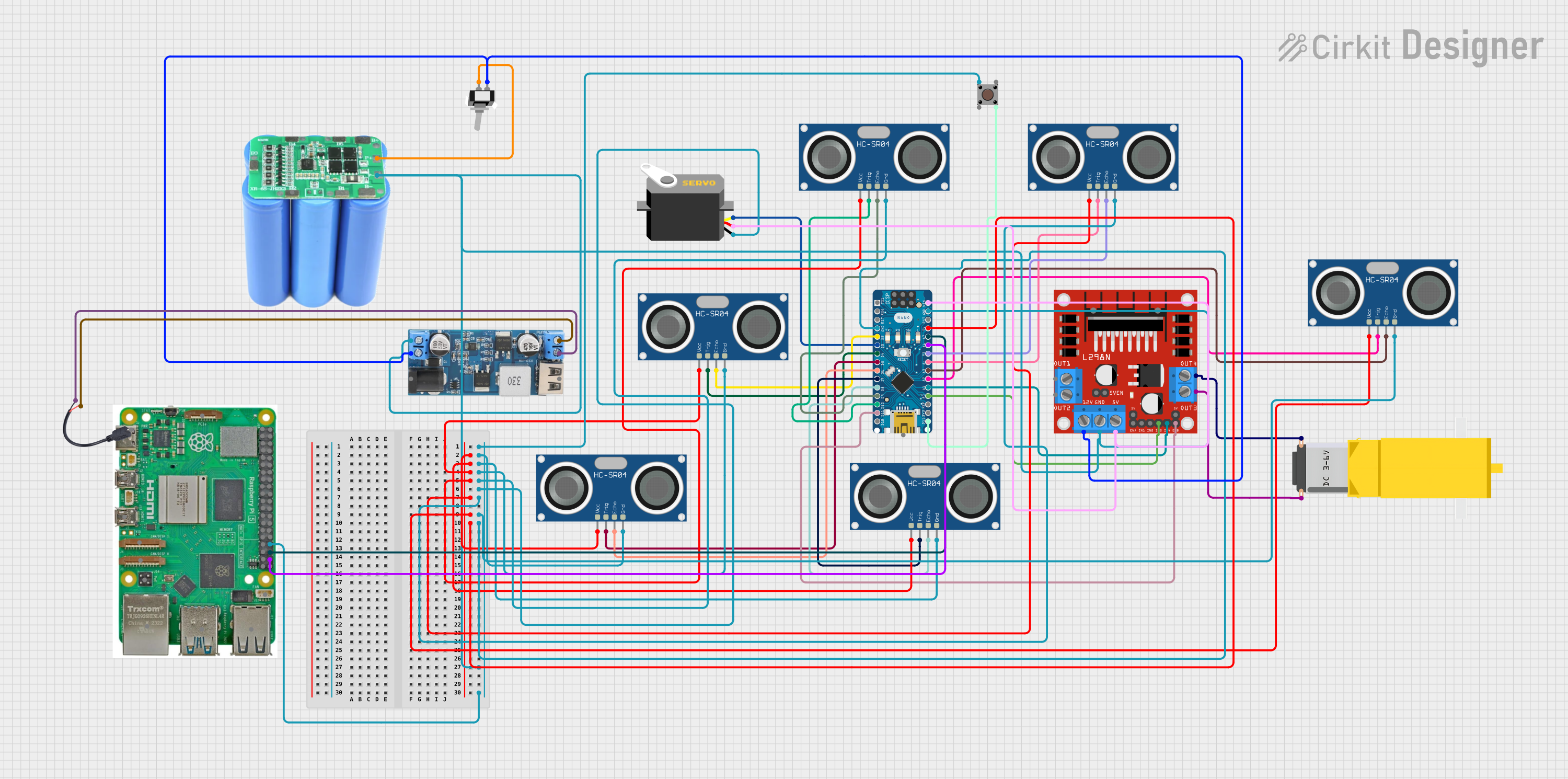
Circuit Documentation
Summary
This circuit integrates a variety of components including an Arduino Nano microcontroller, multiple HC-SR04 ultrasonic sensors, a servo motor, a pushbutton, an L298N DC motor driver, a gearmotor, a toggle switch, a power source (18650 3s2p battery pack), a step-down power converter, a Raspberry Pi 5, and a micro USB to cable connector. The primary function of this circuit is not explicitly stated, but it appears to be designed for distance measurement, motor control, and interfacing with a Raspberry Pi for advanced processing or control.
Component List
Microcontroller
- Arduino Nano: A compact microcontroller board based on the ATmega328P, featuring digital and analog I/O pins.
Sensors
- HC-SR04 Ultrasonic Sensors: Ultrasonic distance measurement modules that provide 2cm to 400cm non-contact measurement functionality.
Actuators
- Servo: A rotary actuator or linear actuator that allows for precise control of angular or linear position.
Motor Control
- L298N DC Motor Driver: A high-power motor driver module that can drive up to two DC motors.
Motors
- Gearmotor DC / Motorreductor: A DC motor with a gearbox attached to its shaft.
Switches
- Pushbutton: A simple switch mechanism for controlling some aspect of a machine or a process.
- Toggle Switch SPST: A single pole single throw (SPST) switch that can connect or disconnect the circuit.
Power
- 18650 3s2p: A battery pack configuration with 18650 cells in a 3 series 2 parallel arrangement.
- 12v to 5v Step Down Power Converter: A module that steps down voltage from 12V to 5V.
Computing
- Raspberry Pi 5: A small single-board computer with a broad set of capabilities including GPIO pins.
Connectors
- Micro USB to Cable (2 Pin): A cable with a micro USB connector on one end and two pins on the other.
Wiring Details
Arduino Nano
- Ground connected to various components including ultrasonic sensors, servo, motor driver, and Raspberry Pi.
- 5V output connected to the VCC pins of all HC-SR04 ultrasonic sensors.
- Digital pins D2 to D10 and analog pins A0 to A7 connected to the TRIG and ECHO pins of the HC-SR04 ultrasonic sensors, motor driver control inputs, and Raspberry Pi GPIO pins.
- VIN connected to the servo and motor driver 5V input.
HC-SR04 Ultrasonic Sensors
- VCC pins connected to the Arduino Nano 5V output.
- GND pins connected to the common ground.
- TRIG and ECHO pins connected to specific digital and analog pins on the Arduino Nano for triggering and receiving the ultrasonic signals.
Servo
- GND connected to the common ground.
- VCC connected to the Arduino Nano VIN.
- Pulse connected to the Arduino Nano D3.
L298N DC Motor Driver
- GND and 12V connected to the common ground and power source respectively.
- Motor control inputs (IN3, IN4, ENB) connected to the Arduino Nano.
- Motor outputs (OUT3, OUT4) connected to the gearmotor.
Gearmotor DC / Motorreductor
- Connected to the L298N DC motor driver outputs.
Pushbutton
- One side connected to the Arduino Nano D13/SCK.
- The other side connected to the common ground.
Toggle Switch SPST
- One terminal connected to the power source positive terminal.
- The other terminal connected to the step-down converter VIN+ and motor driver 12V input.
18650 3s2p
- Positive terminal connected to the toggle switch.
- Negative terminal connected to the common ground.
12v to 5v Step Down Power Converter
- VIN+ connected to the toggle switch.
- VIN- connected to the common ground.
- 5V output connected to the micro USB to cable connector.
Raspberry Pi 5
- GPIO pins 16 and 20 connected to the Arduino Nano A7 and A6 respectively.
- GND connected to the common ground.
Micro USB to Cable (2 Pin)
- Positive and negative pins connected to the 5V output and GND of the step-down power converter.
Documented Code
Arduino Nano Code (sketch.ino)
void setup() {
  // put your setup code here, to run once:

}

void loop() {
  // put your main code here, to run repeatedly:

}
Note: The provided code for the Arduino Nano is a template with empty setup and loop functions. To fully document the code, the specific functionalities and logic for interacting with the connected components would need to be implemented and described.