
ESP8266 NodeMCU-Based Smart Gardening System with Environmental Sensors and Water Pump Control
View and Edit Project In Cirkit Designer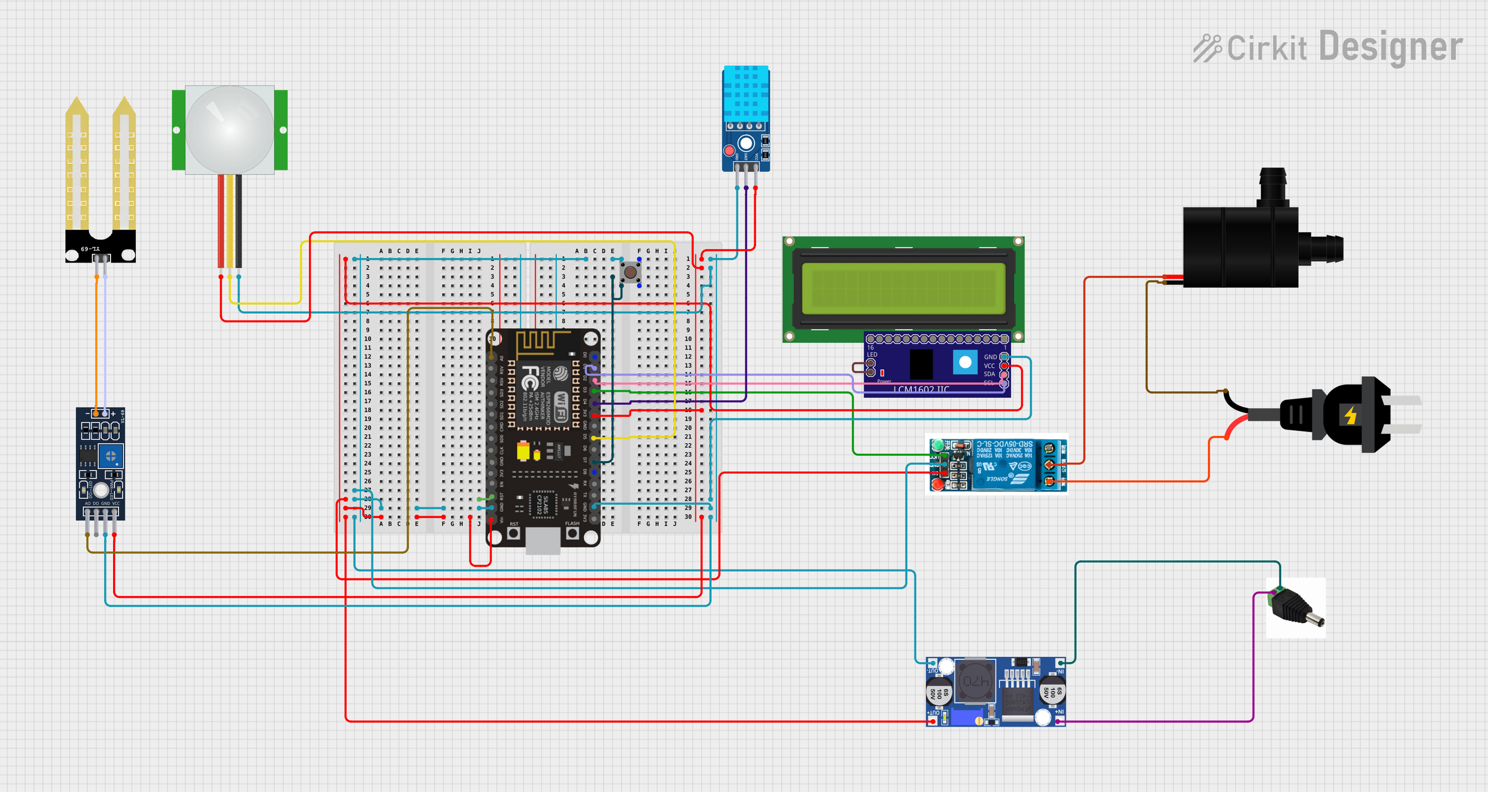
Circuit Documentation
Summary of the Circuit
This circuit appears to be designed for environmental monitoring and control, featuring a variety of sensors and actuators. The core of the circuit is an ESP8266 NodeMCU microcontroller, which is responsible for interfacing with the various components, including a DHT11 temperature and humidity sensor, a PIR motion sensor, a soil moisture sensor (YL-69), and a relay-controlled water pump. The circuit also includes a pushbutton for user input, an LCD display for output, and a buck converter to regulate the power supply. The ESP8266 NodeMCU is powered by a DC source through the buck converter, and it controls the relay to switch an AC source that powers the water pump. The LCD display is interfaced via an I2C adapter for simplified communication.
Component List
DC Power Input
- DC PIN: A connector for the DC power supply.
AC Power Source
- AC source: Provides alternating current for the relay-controlled water pump.
Microcontroller
- ESP8266 NodeMCU: A Wi-Fi-enabled microcontroller with multiple GPIO pins for interfacing with sensors, actuators, and communication modules.
Power Regulation
- Buck converter: Steps down the voltage from the DC power input to a lower voltage suitable for the microcontroller and other components.
Relay Module
- 5V Relay: An electromechanical switch that allows the microcontroller to control high-power devices such as the water pump.
Display
- LCD Display 16x2: A 16-character by 2-line display for showing information.
- LCM1602 IIC: An I2C interface adapter for the LCD display, simplifying the connection to the microcontroller.
Sensors
- DHT11 Sensor V2: Measures temperature and humidity.
- PIR sensor: Detects motion based on infrared signals.
- YL-69 Module LM393: A soil moisture sensor module.
- YL-69 Sonda: The probe part of the soil moisture sensor.
Actuator
- Water Pump: An electric pump controlled by the relay for watering purposes.
User Input
- Pushbutton: A simple pushbutton for user interaction.
Wiring Details
DC Power Input
- DC PIN
-ve: Connected to the buck converter'sIN-.+ve: Connected to the buck converter'sIN+.
AC Power Source
- AC source
-: Connected to the relay'sNormally Open.+: Connected to the water pump'sGND.
Microcontroller
- ESP8266 NodeMCU
GND: Common ground for the pushbutton, relay, buck converter, and other GND connections.VIN: Connected to the buck converter'sOUT+.3V3: Powers the DHT11 sensor, PIR sensor, and YL-69 Module LM393.RST: Reset pin (not connected to other components).D0-D8, RX, TX, A0, RSV, SD3, SD2, SD1, CMD, SD0, CLK, EN: General purpose I/O pins, some are used for interfacing with sensors and the relay.D7: Connected to the pushbutton'sPin 2 (in).D3: Powers the relay'sVCC.D1: Connected to the LCM1602 IIC'sSCL.D2: Connected to the LCM1602 IIC'sSDA.D4: Connected to the DHT11 sensor'sDAT.D5: Connected to the PIR sensor'sSIG.A0: Connected to the YL-69 Module LM393'sA0.
Power Regulation
- Buck converter
IN+: Connected to the DC PIN's+ve.IN-: Connected to the DC PIN's-ve.OUT+: Powers the microcontroller'sVINand the relay'sIn.OUT-: Common ground connection.
Relay Module
- 5V Relay
Normally Open: Connected to the AC source's-.Common terminal: Connected to the water pump'sVCC.Normally Closed: Not connected.In: Powered by the buck converter'sOUT+.GND: Common ground connection.VCC: Powered by the microcontroller'sD3.
Display
- LCD Display 16x2: Not directly wired in the provided net list.
- LCM1602 IIC
GND: Common ground connection.VCC: Powered by the microcontroller'sVIN.SDA: Connected to the microcontroller'sD2.SCL: Connected to the microcontroller'sD1.LED_A,LED_B: Backlight control (connected together).
Sensors
- DHT11 Sensor V2
GND: Common ground connection.DAT: Connected to the microcontroller'sD4.VCC: Powered by the microcontroller's3V3.
- PIR sensor
GND: Common ground connection.SIG: Connected to the microcontroller'sD5.VDD: Powered by the microcontroller's3V3.
- YL-69 Module LM393
A0: Connected to the microcontroller'sA0.DO: Not connected in the provided net list.GND: Common ground connection.VCC: Powered by the microcontroller's3V3.-: Connected to the YL-69 Sonda's-.+: Connected to the YL-69 Sonda's+.
- YL-69 Sonda
-: Connected to the YL-69 Module LM393's-.+: Connected to the YL-69 Module LM393's+.
Actuator
- Water Pump
VCC: Connected to the relay'sCommon terminal.GND: Connected to the AC source's+.
User Input
- Pushbutton
Pin 1 (in): Connected to the common ground.Pin 2 (in): Connected to the microcontroller'sD7.Pin 3 (out),Pin 4 (out): Not connected in the provided net list.
Documented Code
No code was provided in the input. The code section would typically include the firmware for the ESP8266 NodeMCU, detailing how it interacts with the sensors, the relay, and the LCD display, as well as any communication protocols used (e.g., I2C for the LCD). It would also include the logic for reading sensor values, controlling the relay, and responding to the pushbutton input.