
Raspberry Pi Pico Controlled Nema 17 Stepper Motor with DRV8825 Driver
View and Edit Project In Cirkit Designer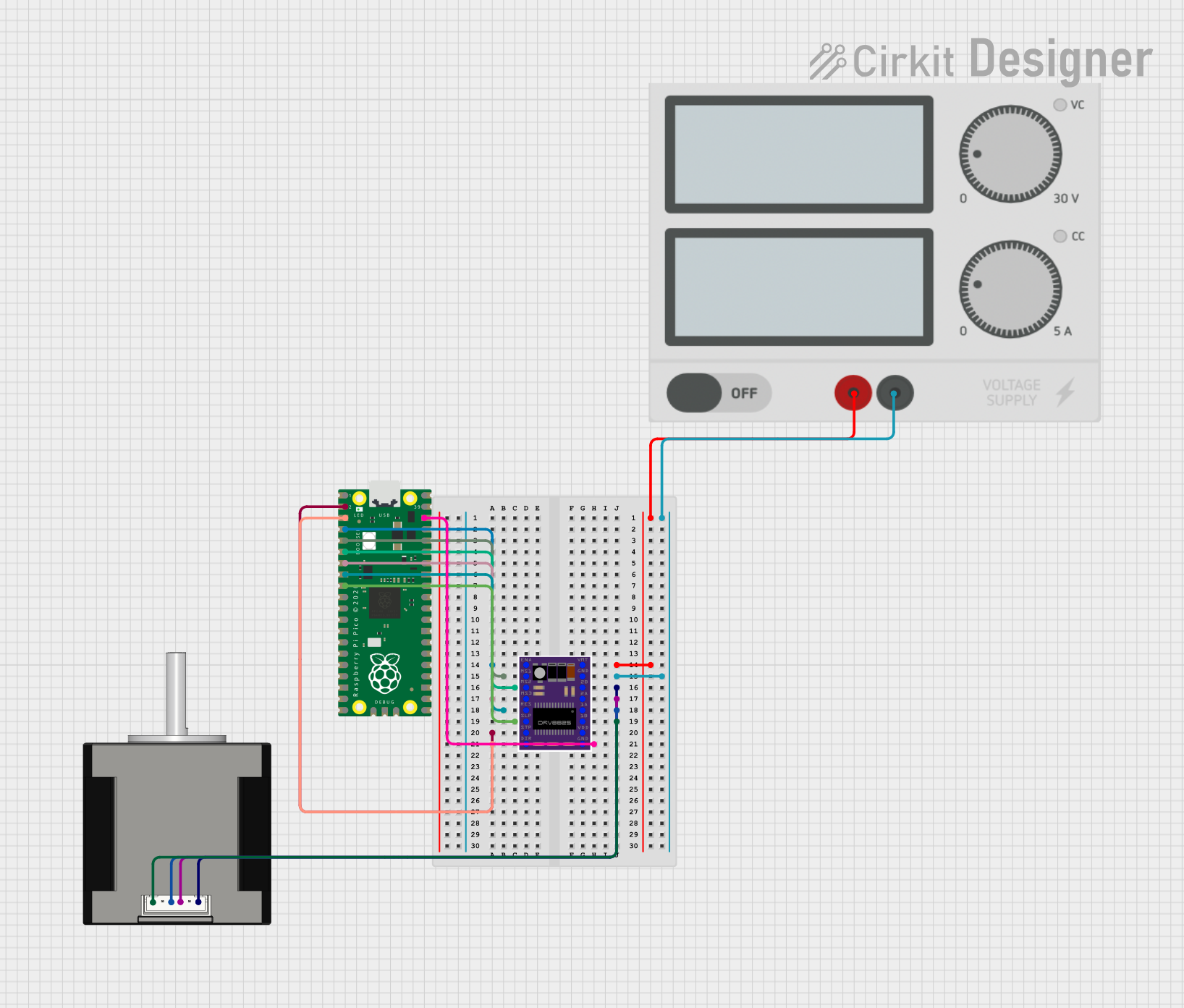
Circuit Documentation
Summary
This document provides a detailed overview of a circuit involving a Raspberry Pi Pico, a DRV8825 stepper motor driver, a Nema 17 stepper motor, and a power supply. The circuit is designed to control the Nema 17 stepper motor using the Raspberry Pi Pico and the DRV8825 driver. The provided Arduino sketch initializes the pins connected to the DRV8825 and performs basic operations to test the motor's functionality.
Component List
Raspberry Pi Pico
- Description: A low-cost, high-performance microcontroller board with flexible digital interfaces.
- Pins: 43 pins including GPIO, power, and ground pins.
Nema 17
- Description: A type of stepper motor commonly used in 3D printers and CNC machines.
- Pins: 4 pins labeled A2 (Black), A1 (Green), b1 (Red), B2 (Blue).
DRV8825
- Description: A stepper motor driver capable of driving a bipolar stepper motor.
- Pins: 15 pins including ENABLE, MS1, MS2, MS3, RESET, SLEEP, STEP, DIR, GND, FAULT, 1B, 1A, 2A, 2B, VMOT.
Power Supply
- Description: Provides the necessary power for the circuit.
- Pins: 2 pins labeled + and -.
Wiring Details
Raspberry Pi Pico
- pin 2: Connected to STEP pin of DRV8825
- pin 3: Connected to DIR pin of DRV8825
- pin 4: Connected to ENABLE pin of DRV8825
- pin 5: Connected to MS1 pin of DRV8825
- pin 6: Connected to MS2 pin of DRV8825
- pin 7: Connected to MS3 pin of DRV8825
- pin 8: Connected to RESET pin of DRV8825
- pin 9: Connected to SLEEP pin of DRV8825
- pin 38: Connected to GND pin of DRV8825
Nema 17
- A2 (Black): Connected to 1B pin of DRV8825
- A1 (Green): Connected to 1A pin of DRV8825
- b1 (Red): Connected to 2A pin of DRV8825
- B2 (Blue): Connected to 2B pin of DRV8825
DRV8825
- VMOT: Connected to + pin of Power Supply
- GND: Connected to - pin of Power Supply and pin 38 of Raspberry Pi Pico
- ENABLE: Connected to pin 4 of Raspberry Pi Pico
- MS1: Connected to pin 5 of Raspberry Pi Pico
- MS2: Connected to pin 6 of Raspberry Pi Pico
- MS3: Connected to pin 7 of Raspberry Pi Pico
- RESET: Connected to pin 8 of Raspberry Pi Pico
- SLEEP: Connected to pin 9 of Raspberry Pi Pico
- STEP: Connected to pin 2 of Raspberry Pi Pico
- DIR: Connected to pin 3 of Raspberry Pi Pico
- 1B: Connected to A2 (Black) pin of Nema 17
- 1A: Connected to A1 (Green) pin of Nema 17
- 2A: Connected to b1 (Red) pin of Nema 17
- 2B: Connected to B2 (Blue) pin of Nema 17
Power Supply
- +: Connected to VMOT pin of DRV8825
- -: Connected to GND pin of DRV8825
Code Documentation
/*
 * This Arduino Sketch is designed to test the circuit involving a Raspberry Pi Pico,
 * a DRV8825 stepper motor driver, and a Nema 17 stepper motor. The code will
 * initialize the pins connected to the DRV8825 and perform basic operations to
 * test the motor's functionality.
 */

// Pin definitions
const int stepPin = 2;
const int dirPin = 3;
const int enablePin = 4;
const int ms1Pin = 5;
const int ms2Pin = 6;
const int ms3Pin = 7;
const int resetPin = 8;
const int sleepPin = 9;
const int gndPin = 38;

void setup() {
  // Initialize serial communication
  Serial.begin(9600);
  Serial.println("Initializing...");

  // Set pin modes
  pinMode(stepPin, OUTPUT);
  pinMode(dirPin, OUTPUT);
  pinMode(enablePin, OUTPUT);
  pinMode(ms1Pin, OUTPUT);
  pinMode(ms2Pin, OUTPUT);
  pinMode(ms3Pin, OUTPUT);
  pinMode(resetPin, OUTPUT);
  pinMode(sleepPin, OUTPUT);
  pinMode(gndPin, OUTPUT);

  // Initialize DRV8825
  digitalWrite(enablePin, LOW); // Enable the driver
  digitalWrite(resetPin, HIGH); // Reset the driver
  digitalWrite(sleepPin, HIGH); // Wake up the driver

  // Set microstepping to full step
  digitalWrite(ms1Pin, LOW);
  digitalWrite(ms2Pin, LOW);
  digitalWrite(ms3Pin, LOW);

  Serial.println("Initialization complete.");
}

void loop() {
  // Test the stepper motor
  Serial.println("Running stepper motor...");
  digitalWrite(dirPin, HIGH); // Set direction
  for (int i = 0; i < 200; i++) { // Rotate 1 revolution (200 steps)
    digitalWrite(stepPin, HIGH);
    delayMicroseconds(1000);
    digitalWrite(stepPin, LOW);
    delayMicroseconds(1000);
  }
  delay(1000); // Wait for a second

  digitalWrite(dirPin, LOW); // Change direction
  for (int i = 0; i < 200; i++) { // Rotate 1 revolution (200 steps)
    digitalWrite(stepPin, HIGH);
    delayMicroseconds(1000);
    digitalWrite(stepPin, LOW);
    delayMicroseconds(1000);
  }
  delay(1000); // Wait for a second
}
This code initializes the pins connected to the DRV8825 and performs basic operations to test the motor's functionality. The motor is rotated in one direction for one revolution and then in the opposite direction for another revolution, with a one-second delay between each direction change.