
ESP32-Based Battery-Powered Health Monitoring System with Wi-Fi Connectivity
View and Edit Project In Cirkit Designer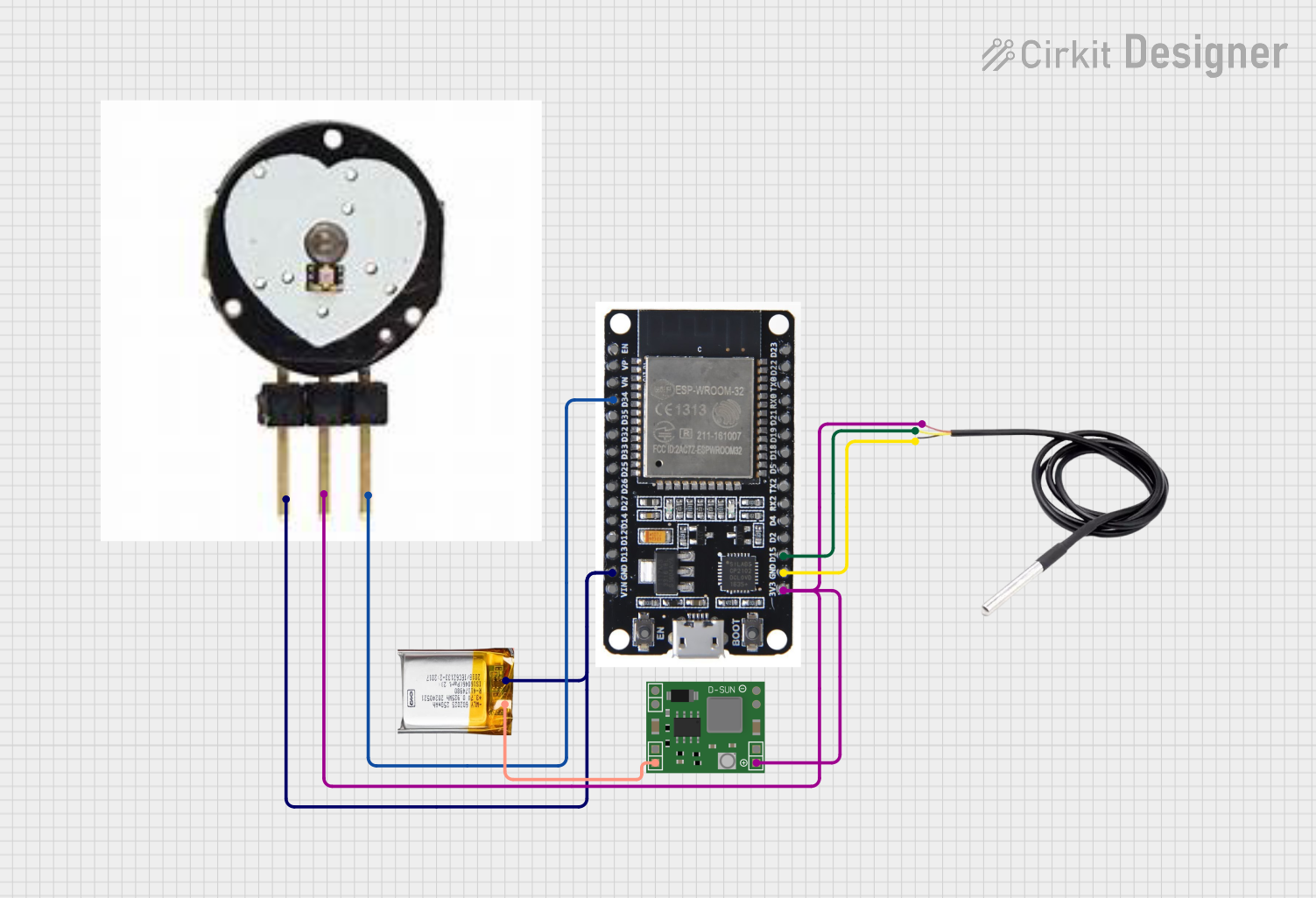
Circuit Documentation
Summary
This circuit is designed to monitor temperature and pulse rate using an ESP32 microcontroller. The temperature is measured using a DS18B20 sensor, and the pulse rate is measured using a pulse sensor. The data is then sent to a Blynk application for remote monitoring. The circuit is powered by a 3.7V LiPo battery, which is regulated to 3.3V using an MP1584EN power regulator board.
Component List
ESP32
- Description: A powerful microcontroller with WiFi and Bluetooth capabilities.
- Pins: EN, VP, VN, D34, D35, D32, D33, D25, D26, D27, D14, D12, D13, GND, VIN, 3V3, D15, D2, D4, RX2, TX2, D5, D18, D19, D21, RX0, TX0, D22, D23, BOOT
Pulse Sensor
- Description: A sensor used to measure pulse rate.
- Pins: gnd, vcc, ao
DS18B20
- Description: A digital temperature sensor.
- Pins: signal, GND, vcc
3.7V LiPo Battery
- Description: A rechargeable lithium polymer battery.
- Pins: +Ve, GND
MP1584EN Power Regulator Board
- Description: A power regulator board used to step down voltage.
- Pins: IN -, IN +, OUT +, OUT -
Wiring Details
ESP32
- D34: Connected to
aoof Pulse Sensor - GND: Connected to
GNDof 3.7V LiPo Battery,gndof Pulse Sensor, andGNDof DS18B20 - 3V3: Connected to
vccof DS18B20,vccof Pulse Sensor, andOUT +of MP1584EN Power Regulator Board - D15: Connected to
signalof DS18B20
Pulse Sensor
- gnd: Connected to
GNDof 3.7V LiPo Battery andGNDof ESP32 - vcc: Connected to
3V3of ESP32 andOUT +of MP1584EN Power Regulator Board - ao: Connected to
D34of ESP32
DS18B20
- signal: Connected to
D15of ESP32 - GND: Connected to
GNDof ESP32 - vcc: Connected to
3V3of ESP32 andOUT +of MP1584EN Power Regulator Board
3.7V LiPo Battery
- GND: Connected to
GNDof ESP32 andgndof Pulse Sensor - +Ve: Connected to
IN +of MP1584EN Power Regulator Board
MP1584EN Power Regulator Board
- IN +: Connected to
+Veof 3.7V LiPo Battery - OUT +: Connected to
3V3of ESP32,vccof DS18B20, andvccof Pulse Sensor
Code Documentation
Sketch Code (sketch.ino)
#define BLYNK_PRINT Serial
#include <WiFi.h>
#include <WiFiClient.h>
#include <BlynkSimpleEsp32.h>
#include <OneWire.h>
#include <DallasTemperature.h>

// Blynk Auth Token
char auth[] = "YourAuthToken";

// Your WiFi credentials.
char ssid[] = "YourNetworkName";
char pass[] = "YourPassword";

// DS18B20 Temperature Sensor
#define ONE_WIRE_BUS 15 // DS18B20 signal pin
OneWire oneWire(ONE_WIRE_BUS);
DallasTemperature sensors(&oneWire);

// Pulse Sensor
#define PULSE_PIN 34 // Pulse sensor analog output pin

BlynkTimer timer;

void sendSensorData()
{
  // Request temperature from DS18B20
  sensors.requestTemperatures();
  float temperature = sensors.getTempCByIndex(0);

  // Read pulse value from Pulse Sensor
  int pulseValue = analogRead(PULSE_PIN);

  // Send data to Blynk
  Blynk.virtualWrite(V1, temperature); // Send temperature to Blynk app
  Blynk.virtualWrite(V2, pulseValue);  // Send pulse value to Blynk app

  // Debug prints
  Serial.print("Temperature: ");
  Serial.print(temperature);
  Serial.print(" °C, Pulse: ");
  Serial.println(pulseValue);
}

void setup()
{
  // Debug console
  Serial.begin(115200);

  // Initialize Blynk
  Blynk.begin(auth, ssid, pass);

  // Initialize DS18B20 sensor
  sensors.begin();

  // Setup a function to be called every second
  timer.setInterval(1000L, sendSensorData);
}

void loop()
{
  // Run Blynk
  Blynk.run();

  // Run timer
  timer.run();
}
This code initializes the ESP32 microcontroller, connects to a WiFi network, and sets up the DS18B20 temperature sensor and the pulse sensor. It reads the temperature and pulse values every second and sends the data to the Blynk application for remote monitoring. The data is also printed to the serial console for debugging purposes.