
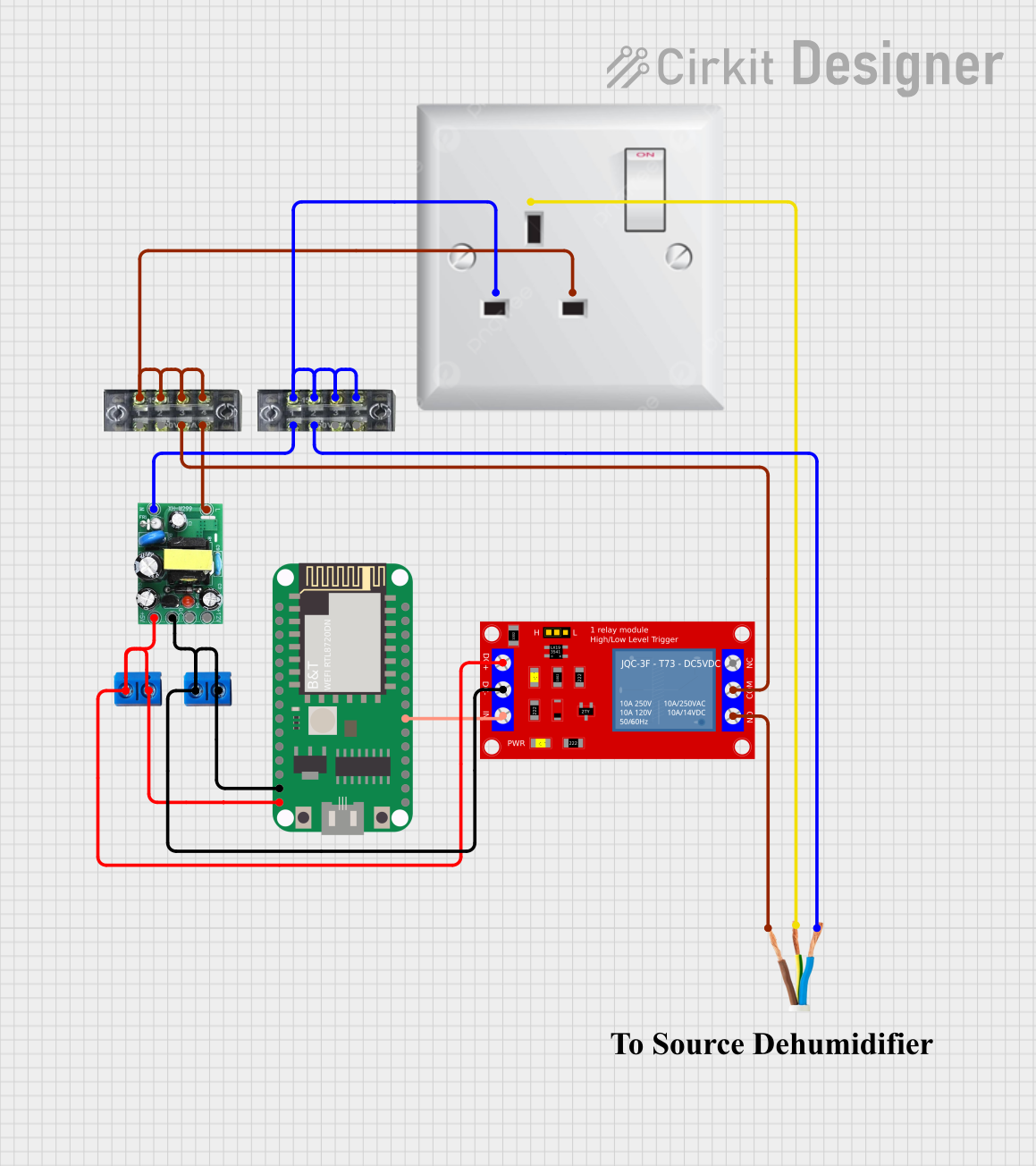
Circuit Documentation
Summary
The circuit described in the provided information consists of several components that work together to control a relay module using a microcontroller. The microcontroller is powered by a 5V supply from an AC-DC PSU board, which also provides a 12V output. The AC-DC PSU board is connected to an AC wall plug point through terminal blocks. The relay module is controlled by one of the microcontroller's GPIO pins and can switch an external AC load connected via an AC wire. The circuit does not include any embedded code for the microcontroller, indicating that the functionality of the microcontroller needs to be programmed separately.
Component List
RTL8720DN
- Description: A microcontroller module with WiFi and Bluetooth capabilities.
- Pins: PA15(pin4), CHIP-EN, 3V3, GND, PA12(pin12), PA30(pin3), PA27(pin2), PA14(pin10), PA13(pin11), PA8(pin1), PA26(pin8), NC, VIN, PB2(pin5), PA7(pin0), PA25(pin7), PB3(pin6), PB1(pin4).
AC-DC PSU board 220V-5V&12V
- Description: A power supply unit that converts AC 220V to DC 5V and 12V.
- Pins: AC-N, AC-L, +5V, GND, +12V.
AC wall plug point
- Description: A standard wall plug point for AC power connection.
- Pins: E (Earth), N (Neutral), L (Line).
Terminal Block (04-01)
- Description: A terminal block for connecting and organizing wires.
- Pins: 1, 2, 3, 4, 5, 6, 7, 8.
1 Channel 5V Relay Module
- Description: A relay module for controlling high power devices.
- Pins: VCC+, VCC- (GND), IN, N.O., COM, N.C.
Terminal PCB 2 Pin
- Description: A 2-pin terminal for PCB mounting.
- Pins: Pin A, Pin B.
AC Wire
- Description: A wire for AC power connection.
- Pins: Line, Earth, Neutral.
Comment
- Description: A placeholder for additional comments or notes.
- Pins: None.
Wiring Details
RTL8720DN
- VIN connected to +5V from AC-DC PSU board and VCC+ of Relay Module.
- GND connected to GND of AC-DC PSU board and VCC- (GND) of Relay Module.
- PA25(pin7) connected to IN of Relay Module.
AC-DC PSU board 220V-5V&12V
- AC-N connected to terminal block pin 2.
- AC-L connected to terminal block pin 8.
- +5V connected to VIN of RTL8720DN and VCC+ of Relay Module.
- GND connected to GND of RTL8720DN and VCC- (GND) of Relay Module.
AC wall plug point
- E (Earth) connected to Earth of AC Wire.
- N (Neutral) connected to Neutral of AC Wire through terminal block pins 1, 3, 5, 7.
- L (Line) connected to Line of AC Wire through terminal block pins 1, 3, 5, 7.
Terminal Block (04-01)
- Used to connect AC-N and AC-L from the AC-DC PSU board to the AC wall plug point.
- Also used to connect the Earth and Neutral wires from the AC wall plug point to the AC Wire.
1 Channel 5V Relay Module
- VCC+ connected to +5V from AC-DC PSU board.
- VCC- (GND) connected to GND of AC-DC PSU board.
- IN controlled by PA25(pin7) of RTL8720DN.
- COM connected to terminal block pin 6.
- N.O. connected to Line of AC Wire.
Terminal PCB 2 Pin
- Used to distribute +5V and GND to the RTL8720DN and Relay Module.
AC Wire
- Earth connected to E (Earth) of AC wall plug point.
- Neutral connected to terminal block pin 4.
- Line connected to N.O. of Relay Module.
Documented Code
No code was provided for the microcontroller. The functionality of the microcontroller needs to be implemented by the user. The code should handle the initialization of the microcontroller's peripherals, configure the GPIO pin connected to the relay module, and implement the logic to control the relay based on the desired application.
Please note that the above documentation is based on the provided information and assumes standard connections and operations for the components listed. Actual implementation may require additional considerations based on the specific requirements and safety standards of the application.