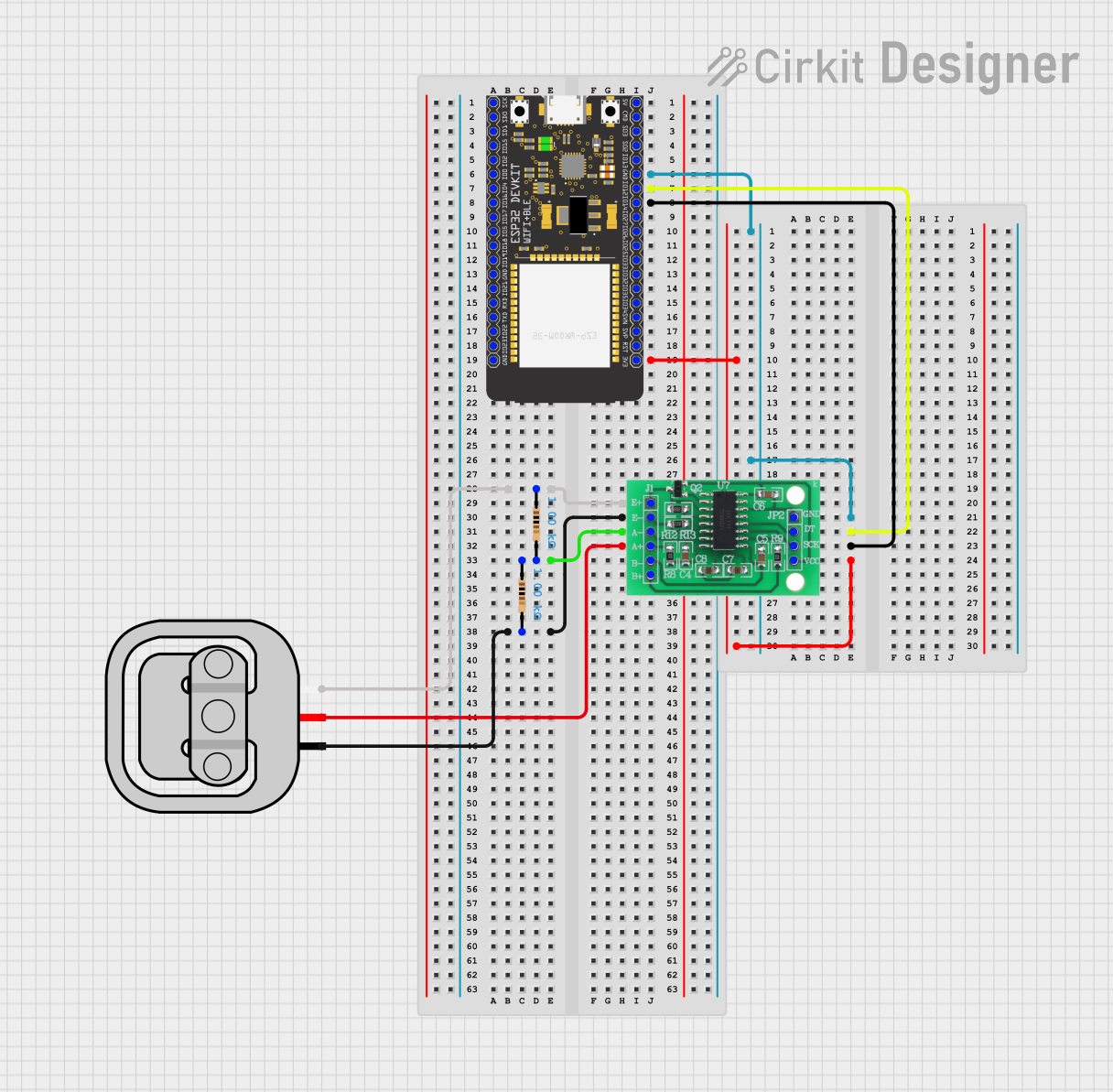
ESP32-Powered Wi-Fi Weight Sensor with HX711 Interface

Circuit Documentation
Summary of the Circuit
This circuit is designed to interface a 50kg load sensor with an ESP32 Wroom microcontroller through an HX711 bridge sensor interface. The HX711 is used to amplify and convert the load sensor's analog signal into a digital form that the ESP32 can process. The ESP32 is responsible for reading the digital data from the HX711 and performing any necessary computations or communications. The circuit also includes two resistors that are likely used for signal conditioning or to set up a reference voltage for the load sensor.
Component List
Resistor
- Description: A standard resistor with a resistance value of 1000 Ohms.
- Purpose: Typically used for current limiting or voltage division in circuits.
Load Sensor - 50kg
- Description: A load sensor capable of measuring weights up to 50 kilograms.
- Purpose: To measure the weight of an object and convert the mechanical force into an electrical signal.
HX711 - Bridge Sensor Interface
- Description: An amplifier and 24-bit analog-to-digital converter designed for bridge sensors like load cells.
- Purpose: To amplify the small signal from the load sensor and convert it to a digital signal that can be read by the microcontroller.
ESP32 Wroom
- Description: A powerful microcontroller with Wi-Fi and Bluetooth capabilities.
- Purpose: To process the digital signal from the HX711 and perform tasks such as data logging, calculations, or wireless communication.
Wiring Details
Resistor
- Connections:
- One end connected to the E+ pin of the HX711 and the W pin of the Load Sensor.
- The other end connected to the A- pin of the HX711.
Load Sensor - 50kg
- Connections:
- W pin connected to the E+ pin of the HX711 through a resistor.
- R pin connected directly to the A+ pin of the HX711.
- B pin connected to the E- pin of the HX711 through another resistor.
HX711 - Bridge Sensor Interface
- Connections:
- E+ pin connected to the W pin of the Load Sensor through a resistor.
- E- pin connected to the B pin of the Load Sensor through a resistor.
- A- pin connected to a resistor.
- A+ pin connected to the R pin of the Load Sensor.
- GND pin connected to the GND pin of the ESP32 Wroom.
- DATA (OUT) pin connected to GPIO12 of the ESP32 Wroom.
- SCK - CLOCK (IN) pin connected to GPIO14 of the ESP32 Wroom.
- 3.3/3.5V Supply pin connected to the 3V3 pin of the ESP32 Wroom.
ESP32 Wroom
- Connections:
- GND pin connected to the GND pin of the HX711.
- GPIO12 connected to the DATA (OUT) pin of the HX711.
- GPIO14 connected to the SCK - CLOCK (IN) pin of the HX711.
- 3V3 pin connected to the 3.3/3.5V Supply pin of the HX711.
Documented Code
Microcontroller Code (ESP32 Wroom)
void setup() {
  // put your setup code here, to run once:

}

void loop() {
  // put your main code here, to run repeatedly:

}
Filename: sketch.ino
Description: This is a template for the ESP32 Wroom microcontroller code. The setup() function is called once when the microcontroller is powered on or reset. The loop() function is called repeatedly and contains the main logic of the program. The actual implementation should include initializing the HX711 interface and reading the data from the load sensor.
Note: The provided code is a placeholder and does not contain any functional implementation. It needs to be completed with the logic for interfacing with the HX711 and processing the load sensor data.